00196504-02_UM_X-Serie_SR70X_EN.pdf - 第248页
Setting up and commissioning User manual SIPLACE X-series Setting up the machine From software version SR.70x.xx 01/2011 EN edition 248 4.3.8.4 X3 axis unit (gantry 3) - connecting the plugs → Connect the power cable as …
User manual SIPLACE X-series Setting up and commissioning
From software version SR.70x.xx 01/2011 EN edition Setting up the machine
247
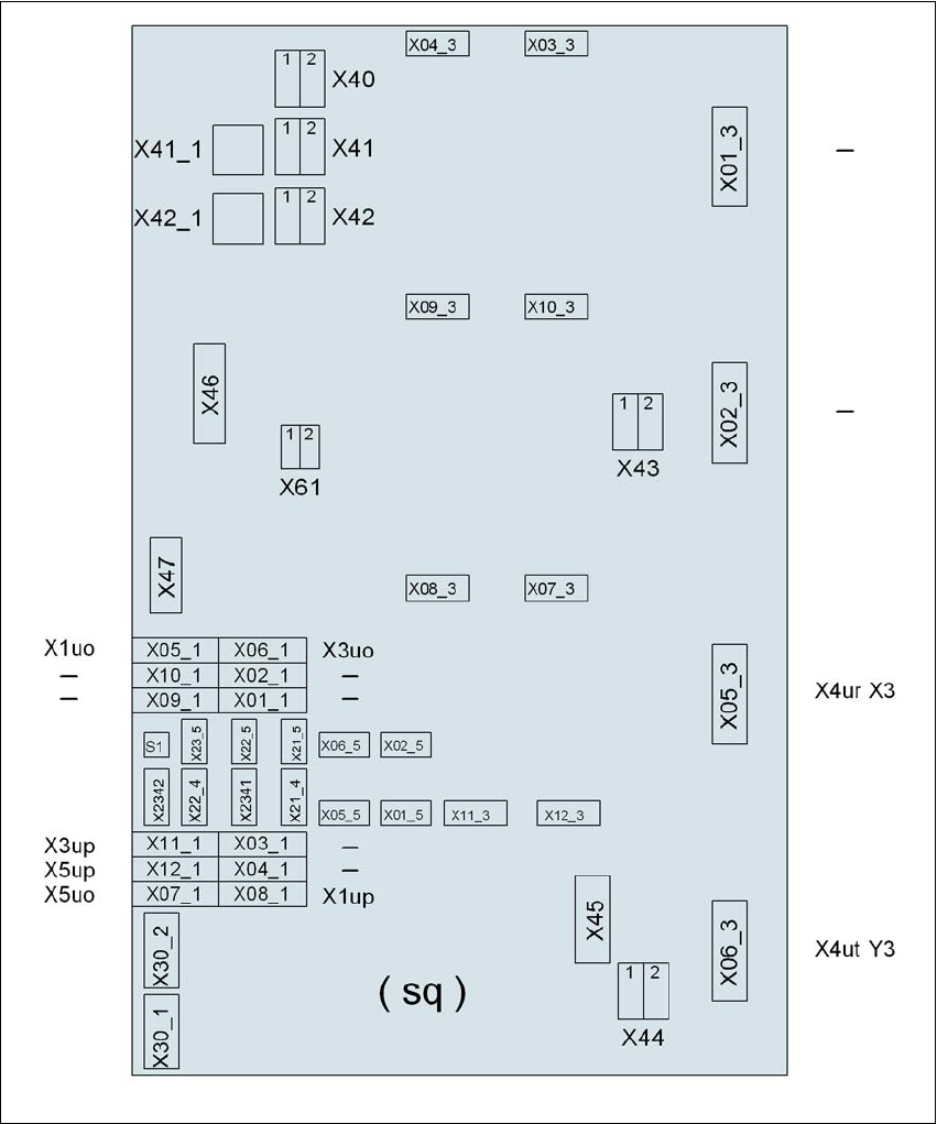
4.3.8.3 X3 axis unit (gantry 3) - electrical connection points
4
4
Fig. 4.3 - 12 X3 axis unit (gantry 3), back panel - electrical connection points
Plug
Plug
Plug

Setting up and commissioning User manual SIPLACE X-series
Setting up the machine From software version SR.70x.xx 01/2011 EN edition
248
4.3.8.4 X3 axis unit (gantry 3) - connecting the plugs
→ Connect the power cable as shown in the following diagram:
4
4
→ Check the switch settings for S1
1: ON
2: Not used
→ Continue from Section 4.3.8.7
"Fitting the axis unit", page 251.
Axis unit, plugs Connecting cable Please note
Plug Cable
X41_1sq X41_1sq 03050899 Snap connector into place
X42_1sq X42_1sq 03050899 Snap connector into place
X45sq X45sq 03050900-W1 Snap connector into place
X46sq X46sq
03050900-W2
03050900-W3
Snap connector into place
X47sq X47sq
03050900-W4
03050900-W5
Snap connector into place
X05_3sq X4ur 03050901 Snap connector into place
X06_3sq X4ut 03050902 Snap connector into place
X05_1sq X1uo 03009811 Insert as far as the stop
X06_1sq X3uo 03009812 Insert as far as the stop
X07_1sq X5uo 03009813 Insert as far as the stop
X08_1sq X1up 03009814 Insert as far as the stop
X11_1sq X3up 03009815 Insert as far as the stop
X12_1sq X5up 03009816 Insert as far as the stop
X07_3sq X07_3sq 03050903 Snap connector into place
X08_3sq X08_3sq 03050904 Snap connector into place
X11_3sq X11_3sq 03050906 Snap connector into place
X12_3sq X12_3sq 03050905 Snap connector into place
X30_1sq X30_1sq 03010054 Screw tightly
X30_2sq X30_2sq 03010054 Screw tightly
User manual SIPLACE X-series Setting up and commissioning
From software version SR.70x.xx 01/2011 EN edition Setting up the machine
249
4.3.8.5 Axis unit X4I, X4 (gantry 2 and gantry 3) - electrical connection points
4
Fig. 4.3 - 13 Axis unit X4I, X4 (gantry 2 and gantry 3), rear panel - electrical connection points
Plug
Plug
Plug