00196504-02_UM_X-Serie_SR70X_EN.pdf - 第251页
User manual SIPLACE X-series Setting up and commissioning From software version SR.70x.xx 01/2011 EN edition Setting up the machine 251 → Check the switch settings for S1 1: ON 2: Not used 4.3.8.7 Fitting the axis unit →…

Setting up and commissioning User manual SIPLACE X-series
Setting up the machine From software version SR.70x.xx 01/2011 EN edition
250
4.3.8.6 Axis unit X4I, X4 (gantry 2 and gantry 3) - connecting the plugs
→ Connect the power cable as shown in the following diagram:
4
Axis unit, plugs Connecting cable Please note
Plug Cable
X41_1sq X41_1sq 03050899 Snap connector into place
X42_1sq X42_1sq 03050899 Snap connector into place
X45sq X45sq 03050900-W1 Snap connector into place
X46sq X46sq
03050900-W2
03050900-W3
Snap connector into place
X47sq X47sq
03050900-W4
03050900-W5
Snap connector into place
X01_3sq X4tr 03050891 Snap connector into place
X02_3sq X4tt 03050892 Snap connector into place
X05_3sq X4ur 03050901 Snap connector into place
X06_3sq X4ut 03050902 Snap connector into place
X01_1sq X1to 03009791 Insert as far as the stop
X02_1sq X3to 03009792 Insert as far as the stop
X03_1sq X5to 03009793 Insert as far as the stop
X04_1sq X1tp 03009794 Insert as far as the stop
X05_1sq X1uo 03009811 Insert as far as the stop
X06_1sq X3uo 03009812 Insert as far as the stop
X07_1sq X5uo 03009813 Insert as far as the stop
X08_1sq X1up 03009814 Insert as far as the stop
X09_1sq X3tp 03009795 Insert as far as the stop
X10_1sq X5tp 03009796 Insert as far as the stop
X11_1sq X3up 03009815 Insert as far as the stop
X12_1sq X5up 03009816 Insert as far as the stop
X03_3sq X03_3sq 03050893 Snap connector into place
X04_3sq X04_3sq 03050894 Snap connector into place
X07_3sq X07_3sq 03050903 Snap connector into place
X08_3sq X08_3sq 03050904 Snap connector into place

User manual SIPLACE X-series Setting up and commissioning
From software version SR.70x.xx 01/2011 EN edition Setting up the machine
251
→ Check the switch settings for S1
1: ON
2: Not used
4.3.8.7 Fitting the axis unit
→ Carefully lift the axis unit onto the rail in the extension kit.
→ Make sure that you do not squash any cables.
→ Push the axis unit into the extension kit as far as the stop.
→ Secure the axis unit with the fillister head screw.
→ Insert the cover.
→ Fix the grounding cable to the doors (item 2 in Fig. 4.3 - 8
, page 239),
as shown in Fig. 4.3 - 9
on page 242.
→ Lock the doors.
4.3.8.8 Fitting the side plates
→ Fix the grounding cable to each side plate (item 6 in Fig. 4.3 - 8, page 239), as shown in Fig.
4.3 - 9
page 242.
→ Fix the side plate to the machine frame with 6 fillister head screws.
PLEASE NOTE 4
If you have dismantled the output conveyor, continue from Section 4.3.9
" Fitting the input con-
veyor" on page 252.
Once the input conveyor is fitted, then continue the assembly work from Section 4.3.14
"Fitting
the indicator lamp" on page 268.
X09_3sq X09_3sq 03050896 Snap connector into place
X10_3sq X10_3sq 03050895 Snap connector into place
X11_3sq X11_3sq 03050906 Snap connector into place
X12_3sq X12_3sq 03050905 Snap connector into place
X30_1sq X30_1sq 03010054 Screw tightly
X30_2sq X30_2sq 03010054 Screw tightly
Axis unit, plugs Connecting cable Please note
Plug Cable
Setting up and commissioning User manual SIPLACE X-series
Setting up the machine From software version SR.70x.xx 01/2011 EN edition
252
4.3.9 Fitting the input conveyor
4.3.9.1 Tools
– Allen keys, DIN 911, set
– Phillips screwdriver, size 1
4.3.9.2 Assembly
4
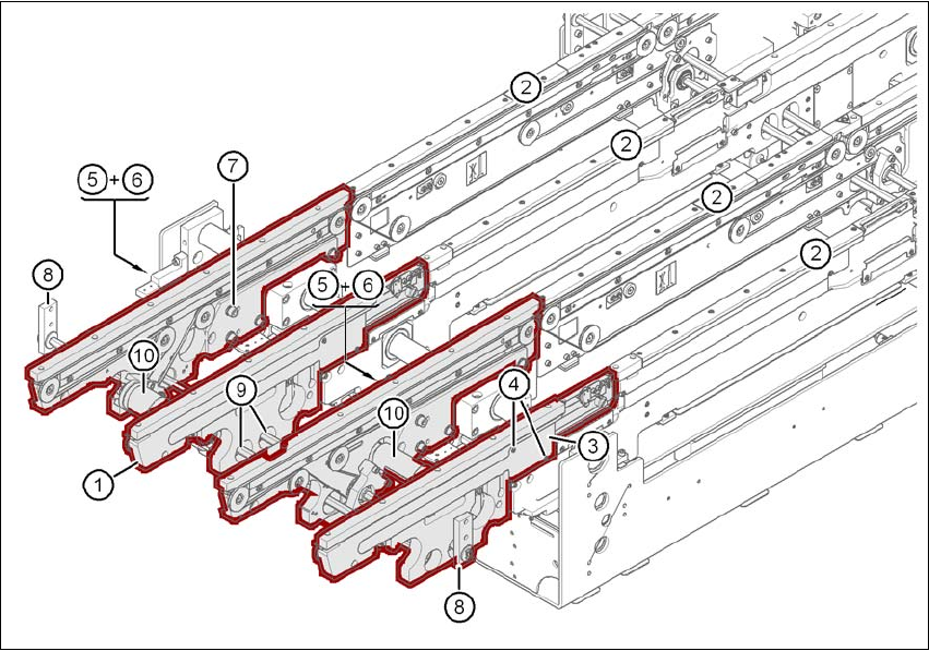
Fig. 4.3 - 14 Input conveyor - dual conveyor
(1) Rail, input conveyor
(2) rail, processing conveyor 1
(3) Cable cover 20 x 200
(4) Countersunk screw, ISO 7046, M3x6, 2x per cable cover
(5) Cable cover 20 x 310
(6) Fillister head screw DIN 912, M3x5, 1x per cable cover
(7) Fillister head screw DIN 912, M6x16, and washer, 4x per rail
(8) Guide for hexagonal shaft
(9) Hexagonal shaft (single conveyor: one, dual conveyor: two)
(10) Drive unit