00196504-02_UM_X-Serie_SR70X_EN.pdf - 第256页
Setting up and commissioning User manual SIPLACE X-series Setting up the machine From software version SR.70x.xx 01/2011 EN edition 256 4.3.10.3 Fitting the guide for the hexagonal shaf t → On the single conveyor , fix o…
User manual SIPLACE X-series Setting up and commissioning
From software version SR.70x.xx 01/2011 EN edition Setting up the machine
255
→ Release the two horizontal tensioners (item 6 in Fig. 4.3 - 15, page 254).
CAUTION 4
Do not unscrew the three bottom screws straight away. Simply loosen them so that the side
plate does not fall off.
→ Detach the ground cable from the side plate.
→ Remove both doors (item 2 in Fig. 4.3 - 15
, page 254) from the extension kit (item 1).
PLEASE NOTE: 4
To avoid damage, we recommend that a second person helps to assemble the extension kit.
→ Set down the box PC unit
a
(item 8 in Fig. 4.3 - 15, page 254) and the axis unit (item 9 in Fig.
4.3 - 15
, page 254) at the side of the machine in order to make enough space to fit the exten-
sion kit (item 1 in Fig. 4.3 - 15
, page 254).
→ Make sure that the connecting cables to the box PC unit and axis unit are not too tight.
→ Lift the extension kit (item 1 in Fig. 4.3 - 15
, page 254) against the machine frame and position
it so that the assembly bracket lies on the drawer unit rail (item 7 in Fig. 4.3 - 15
, page 254).
CAUTION 4
Make sure that the extension kit does not collide with the hexagonal shaft of the PCB con-
veyor and thus become bent.
→ Fix the extension kit using 4 fillister head screws M6x16 and the associated washers (item 3
in Fig. 4.3 - 15
, page 254).
a) see Section 4.3.12, page 263

Setting up and commissioning User manual SIPLACE X-series
Setting up the machine From software version SR.70x.xx 01/2011 EN edition
256
4.3.10.3 Fitting the guide for the hexagonal shaft
→ On the single conveyor, fix one guide for the hexagonal shaft (item 8 in Fig. 4.3 - 14, page
252
) to the extension kit using two fillister head screws M6x16 and washers.
→ On the double conveyor, fix two guides for the hexagonal shaft (item 8 in Fig. 4.3 - 14
, page
252
) to the extension kit using two fillister head screws M6x16 and washers.
4.3.10.4 Producing cable connections - extension kit on the PCB input side
4
Left-hand side of the extension kit
(viewed in the direction of travel)
Connector/cable To connector/
cable
Start/stop button
Switch, PCB conveyor cover
X61/03020410 X61/03002537
Protective cover switch, location 4
X54/03020409 X54/03002540
Button for the component trolley docking unit, loca-
tion 4
X242/03021056 X242/03021054
Right-hand side of the extension kit
(viewed in the direction of travel)
Connector/cable To connector/
cable
EMERGENCY STOP button
Start/stop button
X64/03020687 X64/03002538
Protective cover switch, location 1
X51/03020409 X51/03002539
Button for the component trolley docking unit, loca-
tion 1
X212/03021056 X212/03021051
User manual SIPLACE X-series Setting up and commissioning
From software version SR.70x.xx 01/2011 EN edition Setting up the machine
257
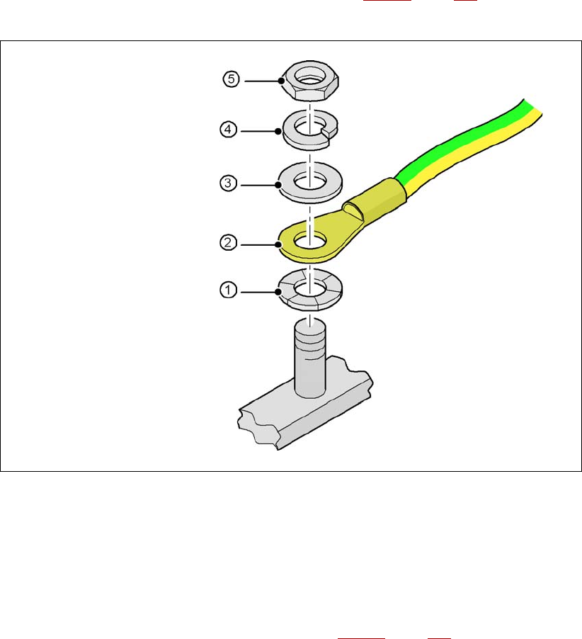
4.3.10.5 Fitting the grounding cable for the doors
→ Fix the two grounding cables for the doors (item 4 in Fig. 4.3 - 15, page 254) to the machine
frame as follows:
4
Fig. 4.3 - 16 Fitting the grounding cable
4
4
4
4
4
4.3.10.6 Checking and setting the protective cover switch
→ Check that the protective cover switch (item 2 in Fig. 4.3 - 17, page 258) is working correctly.
→ Adjust the protective cover switch if necessary (see service manual).
4
Hex nut M5
Spring washer M5, DIN 7980
Washer M5, DIN 125
Cable lug, annular
Contact washer