00196504-02_UM_X-Serie_SR70X_EN.pdf - 第262页
Setting up and commissioning User manual SIPLACE X-series Setting up the machine From software version SR.70x.xx 01/2011 EN edition 262 4.3.1 1.3 Box PC unit X4/X3/X2 - plug-in connectors on the rear p anel 4 4 4.3.1 1.4…

User manual SIPLACE X-series Setting up and commissioning
From software version SR.70x.xx 01/2011 EN edition Setting up the machine
261
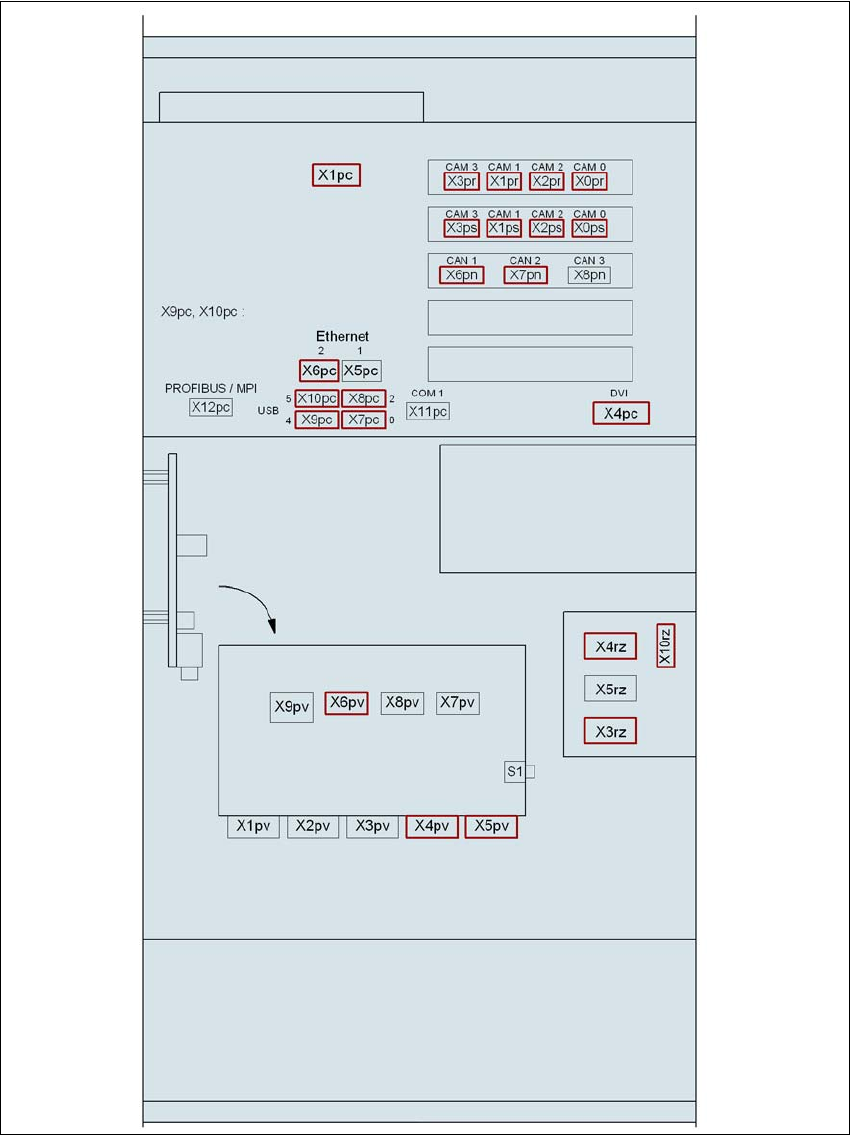
4.3.11.2 Box PC unit X4/X3/X2 - plug-in connectors on the front panel
4
→ Also check the following plug-in connectors:
4
Box PC unit, front panel
(Fig. 4.3 - 20
, page 263)
Plug
Connecting cable Please note
Plug Cable
X0pr
a
X0pr 03009778 Insert as far as the stop
X1pr
a
X1pr 03009838 Insert as far as the stop
X2pr
a
X2pr 03009755 Insert as far as the stop
X3pr
a
X3pr 03009756 Insert as far as the stop
X0ps
a
X0ps 03009798 Insert as far as the stop
X1ps
a
X1ps 03009818 Insert as far as the stop
X2ps
a
X2ps 03009757 Insert as far as the stop
X3ps
a
X3ps 03009758 Insert as far as the stop
X6pc X6pc 03010478 Insert as far as the stop
X5pv X5pv 03051749 Secure with screws
X6pv X6pv 03051750 Secure with screws
a) This plug is intended for cameras.
Box PC unit, front panel (Fig.
4.3 - 20
, page 263)
Plug
Plug Cable
X1pa X4rz (box PC rear panel) 03050908-W2
X1pc X4rz (box PC rear panel) 03050908-W1
X4pa X2pv 03051748
X4pc X1pv 03051747
X5pc X5pa 03051756
X7pc X8pd 03051755
X9pd X2rz (box PC rear panel) 03052633-W1

Setting up and commissioning User manual SIPLACE X-series
Setting up the machine From software version SR.70x.xx 01/2011 EN edition
262
4.3.11.3 Box PC unit X4/X3/X2 - plug-in connectors on the rear panel
4
4
4.3.11.4 Installing the box PC unit on the SIPLACE X4/X3/X2
→ Plug in the plug-in connectors on the rear panel of the box PC unit (see Section 4.3.12.3,
page 265
).
→ Carefully lift the box PC unit onto the rail in the extension kit.
→ Make sure that you do not squash any cables.
→ Push the box PC unit into the extension kit as far as the stop.
→ Plug in the plug-in connectors on the front panel of the box PC unit (see Section 4.3.12.2
,
page 264
).
→ Fix the cables to the front panel with cable ties.
→ Secure the box PC unit with the fillister head screw.
→ Fix the grounding cable to the doors (item 2 in Fig. 4.3 - 15
, page 254),
as shown in Fig. 4.3 - 16
on page 257.
→ Lock the doors.
PLEASE NOTE 4
On X2 machines, continue from Section 4.3.11.5
"Fitting the side plates".
On X3 and X4 machines, continue from Section 4.3.13 "Installing the axis unit" on page 266.
4.3.11.5 Fitting the side plates
→ Fix the grounding cable to each side plate (item 6 in Fig. 4.3 - 15, page 254), as shown in Fig.
4.3 - 16
page 257.
→ Fix the side plate to the machine frame with 6 fillister head screws.
→ Continue from Section 4.3.14
"Fitting the indicator lamp", page 268.
Box PC unit, rear panel
(Fig. 4.3 - 19
, page 260)
Plug
Connecting cable Please note
Plug Cable
PE1 Cable ring Grounding cable
Fix as shown in Fig. 4.3 - 16
,
page 257
.
X1rz X1rz 03051757 Insert as far as the stop
X3rz X3rz 03050907 Insert as far as the stop
X1pd X1pd 03051751 Insert as far as the stop
X2pd X2pd 03051752 Insert as far as the stop
X3pd X3pd 03051753 Insert as far as the stop
X4pd X4pd 03051754 Insert as far as the stop
User manual SIPLACE X-series Setting up and commissioning
From software version SR.70x.xx 01/2011 EN edition Setting up the machine
263
4.3.12 Installing the box PC unit on the SIPLACE X4I
4.3.12.1 Box PC unit - electrical connection points
4
Fig. 4.3 - 20 Box PC unit for SIPLACE X4I, front panel - connecting the plugs
Computer 1
Control computer
0307 1371
box PC unit
0307 2079
Power
supply
for touchscreen
DC/DC converter
0304 8511
Video multiplexer, splitter
0305 7965
Video in 1
Computer 1
Video in 1
Computer 1
Video in 1
Computer 1
3D sensor
Monitor 1
Monitor 2
Voltage distributor
0307 2178
DVD drive