00196504-02_UM_X-Serie_SR70X_EN.pdf - 第279页
User manual SIPLACE X-series Setting up and commissioning From software version SR.70x.xx 01/2011 EN edition Setting up the machine 279 4.3.18 Making final adjustments to the machine → Place the machine's spirit lev…
Setting up and commissioning User manual SIPLACE X-series
Setting up the machine From software version SR.70x.xx 01/2011 EN edition
278
4.3.17.3 Aligning the machine with respect to the line
→ Position the machine on the free location on the line using the fork-lift.
WARNING 4
Lower the machine slowly. A second person should look underneath to ensure that all the
machine foot touch the floor at the same time. If the machine feet on one side hit the ground
hard, the fixings may be damaged.
4
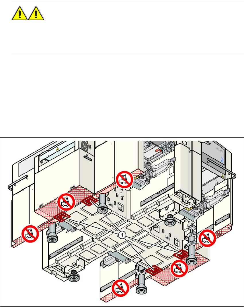
4.3.17.4 Aligning the machine with the air cushion transport system
→ Place the four air cushions of the air cushion transport system beneath the machine frame.
→ Raise the machine and align it with respect to the line.
→ Check the distance from the PCB conveyor system of the adjacent machine. It should be be-
tween 1 mm and 3 mm.
→ Lower the machine.
4
Fig. 4.3 - 30 Contact positions for the air cushion transport system
(1) Contact surfaces for the air cushion transport system
User manual SIPLACE X-series Setting up and commissioning
From software version SR.70x.xx 01/2011 EN edition Setting up the machine
279
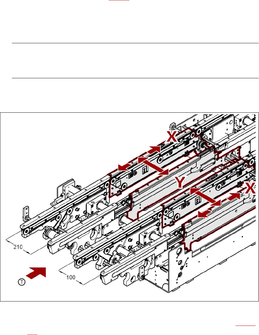
4.3.18 Making final adjustments to the machine
→ Place the machine's spirit level on the rails of the PCB conveyor in placement area 1 in both
the X and the Y directions (see Fig. 4.3 - 31
). The PCB conveyor width is preset:
Single conveyor 210 mm
Dual conveyor, track 1 100 mm
Dual conveyor, track 2 210 mm 4
PLEASE NOTE: 4
On the dual conveyor, place the spirit level only on the outer rails of the machine for adjusting
in the X direction.
→ Measure the distance between the top edge of the PCB conveyor belt and the floor. This dis-
tance should be 800 mm, 900 mm, 930 mm or 950 mm.
4
Fig. 4.3 - 31 Adjusting the machine in the X and Y directions
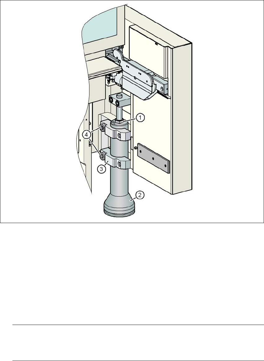
→ Use the size 36 fork wrench to adjust the adjusting screw M24x2x120 (item 1 in Fig. 4.3 - 32,
page 280
) so that the label on the machine spirit level does not deviate from the zero point
for the required PCB conveyor height.
Setting up and commissioning User manual SIPLACE X-series
Setting up the machine From software version SR.70x.xx 01/2011 EN edition
280
4
Fig. 4.3 - 32 Setting the height for the outer machine feet
(1) Adjusting screw M24x2x120 to adjust the height
(2) Outer machine foot
(3) Clamp
(4) M24x90 hexagon socket head screw
→ Check the required PCB conveyor height.
→ If the machine has been aligned, use the torque wrench to tighten the hexagon socket head
screws M24x90 (item 4) for holding the clamps on all the outer machine feet (item 3).
PLEASE NOTE 4
The tightening torque is 130 Nm. The machine may tend to vibrate if a lower tightening torque
is used.
→ Unscrew the middle machine feet using a hook wrench 135 - 145 until they are seated firmly
on the ground.