00196504-02_UM_X-Serie_SR70X_EN.pdf - 第288页
Setting up and commissioning User manual SIPLACE X-series Adapting the used tape channel to the component heigh t From software version SR.70x.xx 01/2011 EN edition 288 4.6.1 Safety instructions WA R N IN G 4 → Switch th…
User manual SIPLACE X-series Setting up and commissioning
From software version SR.70x.xx 01/2011 EN edition Adapting the used tape channel to the component height
287
→ Adjust the extension (item 2 in Fig. 4.5 - 1, page 286) so that the distance between the bottom
edge and the floor does not exceed 320 mm + 20 mm (see Fig. 4.5 - 1
, page 286).
4.6 Adapting the used tape channel to the component
height
If X feeder modules are used, the component tapes work with a pocket height > 12 mm, so the
separating plate (item 1 in Fig. 4.6 - 1
) must be removed.
4
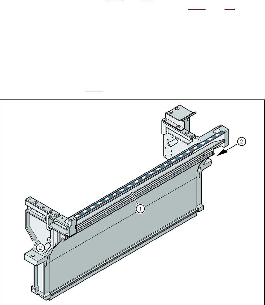
Fig. 4.6 - 1 Used tape channel, SIPLACE X-series
(1) Separating plate for tapes > 12 mm, removable
(2) DIN 93384 screw - M4x20, 2x
Setting up and commissioning User manual SIPLACE X-series
Adapting the used tape channel to the component height From software version SR.70x.xx 01/2011 EN edition
288
4.6.1 Safety instructions
WARNING 4
→ Switch the machine off at the main switch to remove the dividing plate.
→ Disconnect the machine from the power and compressed air supply.
→ Secure the machine to prevent it being switched on again, as described in Section 2.10
, page
94
.
→ Wait until the operating pressure for the tape cutter has dropped to 0 MPa.
→ Do not reach inside the used tape channel.
4.6.2 Removing the separating plate
→ Loosen the two hexagon head screws (item 2 in Fig. 4.6 - 1, page 287).
→ Pull out the separating plate (item 1 in Fig. 4.6 - 1
, page 287).

User manual SIPLACE X-series Setting up and commissioning
From software version SR.70x.xx 01/2011 EN edition Commissioning the machine
289
4.7 Commissioning the machine
4.7.1 Commissioning the machine at the customer's premises
→ Check all modules for correct seating.
→ Wipe off the linear guide rails with a lint-free cloth before removing the shipping braces for the
X/Y axis. Do not use any solvent to do this (see Section 4.3.20
, page 282.
→ Switch on the machine and perform a reference run.
→ Copy the placement program onto the computer and test it.
→ Check the machine zero point after a period of warming up of 3 - 4 h.
→ Get the customer's operating personnel to equip the feeder modules according to the cus-
tomer's placement program.
→ Instruct them in handling the feeder modules using the JobGuide.
→ Check all customer-specific installed options (in particular software) for good functioning and
order any necessary spare parts using the order form or by fax.
4.7.2 Instructing the customer's personnel
→ Explain all customer-specific installed options, in particular software / software compatibility.
→ Explain programming of the program editors on the line computer / SIPLACE Pro.
→ Instruct the operators and line engineers in using the station software.
→ Explain about password protection.
→ Instruct the customer's personnel according to the user manual and the preventive mainte-
nance.
4.7.3 A test run or starting production
→ Test the line using the test PCB or a PCB provided by the customer.
→ Record the customer product and performance data, prepare the data and document the data
in the installation report.
→ Secure the data and give the customer security copies.