00196504-02_UM_X-Serie_SR70X_EN.pdf - 第295页
User manual SIPLACE X-series Tasks on the machine From software version SR.70x.xx 01/ 2011 EN edition Controls and displays 295 5.2 Controls and displays 5.2.1 Position 5 Fig. 5.2 - 1 Controls and displays (1) Operator p…

Tasks on the machine User manual SIPLACE X-series
Personnel profile From software version SR.70x.xx 01/2011 EN edition
294
5.1.3 Operator level "Machine service"
5.1.3.1 Training courses
A list of training courses can be found in Section 1.3, page 30.
5.1.3.2 Tasks
The service personnel's duties include: 5
– Major preventive maintenance jobs
– Mounting replacement parts
– Editing machine data
– Calibrating the machine
5.1.4 Operator level "Programmer"
5.1.4.1 Training courses
A list of training courses can be found in Section 1.3, page 30.
5.1.4.2 Tasks
The programmer's jobs are as follows: 5
– Preparing CAD files
– Creating and calibrating vision data (teaching)
– Writing placement programs
– Implementing a new job
– Data maintenance
– Data backup
User manual SIPLACE X-series Tasks on the machine
From software version SR.70x.xx 01/2011 EN edition Controls and displays
295
5.2 Controls and displays
5.2.1 Position
5
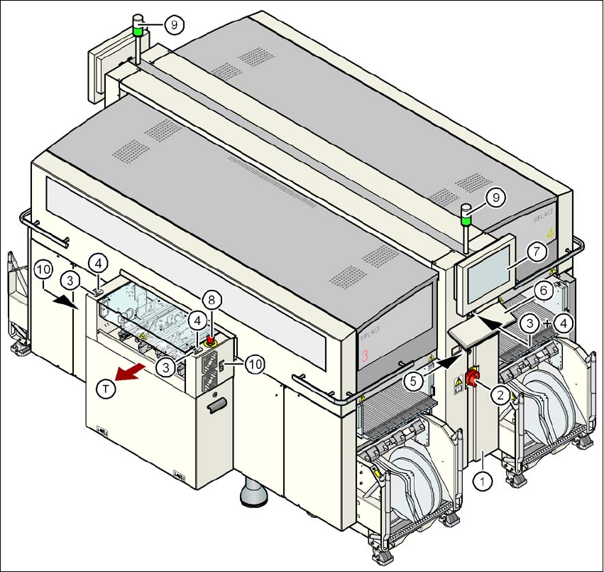
Fig. 5.2 - 1 Controls and displays
(1) Operator panel on the power supply side (7) LCD touchscreen
(2) Main power switch (8) EMERGENCY STOP button
(3) Stop button (black) (9) Indicator lamps
(4) Start button (white) (10) Buttons for docking the component
trolley in and out
(5) Component counter
(6) Keyboard (T) Direction of PCB transport
Tasks on the machine User manual SIPLACE X-series
Controls and displays From software version SR.70x.xx 01/2011 EN edition
296
5.2.2 Description
All the controls can be reached by a 1.40 m tall person.
Main power switch 5
The main power switch is used to switch the power supply to the machine on and off.
WARNING
Some parts inside the machine carry potentially lethal voltages - even when switched off at the
main power switch. 5
Stop button 5
This button is used to stop the machine.
Start button 5
This button starts the machine after it has been switched on or after faults have been eliminated.
EMERGENCY STOP button 5
The emergency stop button latches in the ON position when pressed. The power supply to the
gantry axes, the component trolleys, conveyors and used tape cutters is interrupted and the volt-
age supplied to the star axes of the placement heads is reduced. Turn the button to release it.
Component counter 5
The component counter displays the number of components processed.
LCD touchscreen 5
There is a flat LCD screen with a touch-sensitive surface (touchscreen) on either side of the place-
ment machine.
Keyboard 5
The keyboard is located beneath the monitor.
Indicator lamps 5
The sequence of colors of the indicator lamps is white - green. These lamps are used to signal
operating statuses and malfunctions of the machine.