00196504-02_UM_X-Serie_SR70X_EN.pdf - 第304页
Tasks on the machine User manual SIPLACE X-series Switch off the SIPLACE line From software version SR.70x.xx 01/2011 EN edition 304 5.4 Switch off the SIPLACE line CAUTION AL WA YS carry out the sequence of actions desc…
User manual SIPLACE X-series Tasks on the machine
From software version SR.70x.xx 01/2011 EN edition Switch on the SIPLACE line
303
5
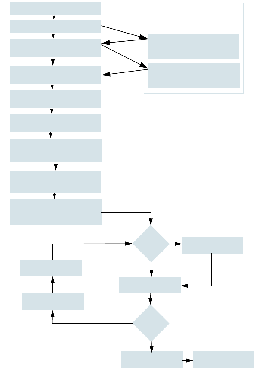
Fig. 5.3 - 2 Flow chart: "Switching on the SIPLACE line"
Station computer
Switch on
Check the set-up
(set feeder modules)
Teach fiducials
Loading PCB data
Press Start button
Waiting for reference run
Move PCB in
Waiting for PCB
Check setup
(if table is highlighted in red)
Change nozzle configuration
if necessary
Nozzle check
Fiducials
OK?
Track -er-
rors
Placement
Check setup
Reset tracks
Placement
PCB to output conveyor
Italics:
This is carried out or
reported by the station
Yes
Yes
No
No
Specifications for the machine
Download wizard
Programming system
tasks
Confirm the conversion on the
Download wizard
Tasks on the machine User manual SIPLACE X-series
Switch off the SIPLACE line From software version SR.70x.xx 01/2011 EN edition
304
5.4 Switch off the SIPLACE line
CAUTION
ALWAYS carry out the sequence of actions described below before you switch off the line. 5
5.4.1 Switch off stations
Follow these steps to switch off the station:
End all placement processes so that there are no more PCBs in the machine.
Check that the Z-axes of all placement heads are in their top end position.
Check whether there are still components at the placement head, and remove these if nec-
essary.
Exit the station computer software from the following view:
Settings --> Machine settings --> Shut down machine...
Once the computer has shut down, switch off the station at the main switch.
5.4.2 Exit SIPLACE Pro (Windows)
On the SIPLACE Pro menu bar, select Object --> Exit.
Close all other programs running on the computer.
Select Shut down machine from the Windows Start menu.
User manual SIPLACE X-series Tasks on the machine
From software version SR.70x.xx 01/2011 EN edition The user interface
305
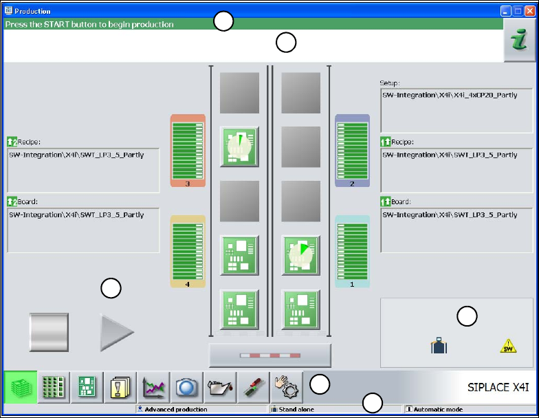
5.5 The user interface
The -user interface is divided into the areas described below.
By way of example, here you can see the user interface in the "Basic production" view for the X4I
machine.
5
Fig. 5.5 - 1 Components of the user interface in the "Basic production" view (in the example of the SIPLACE X4I)
(1) Title bar
(2) Status field (status and error display)
(3) Processing area / display area
(4) Toolbar
(5) Info line
(6) Displays modified configurations and additional options, e.g. barcode mode
5.5.1 Status field
The status field displays the current machine status, the most recent error and the associated ac-
tion required.
The following symbols appear on the right-hand side of the status field, depending on the status:
1
2
3
4
5
6