00196504-02_UM_X-Serie_SR70X_EN.pdf - 第310页
Tasks on the machine User manual SIPLACE X-series The user interface From software version SR.70x.xx 01/2011 EN edition 310 The following view opens: 5 Fig. 5.5 - 4 User interface in the "Nozzle changer" vie w …
User manual SIPLACE X-series Tasks on the machine
From software version SR.70x.xx 01/2011 EN edition The user interface
309
5
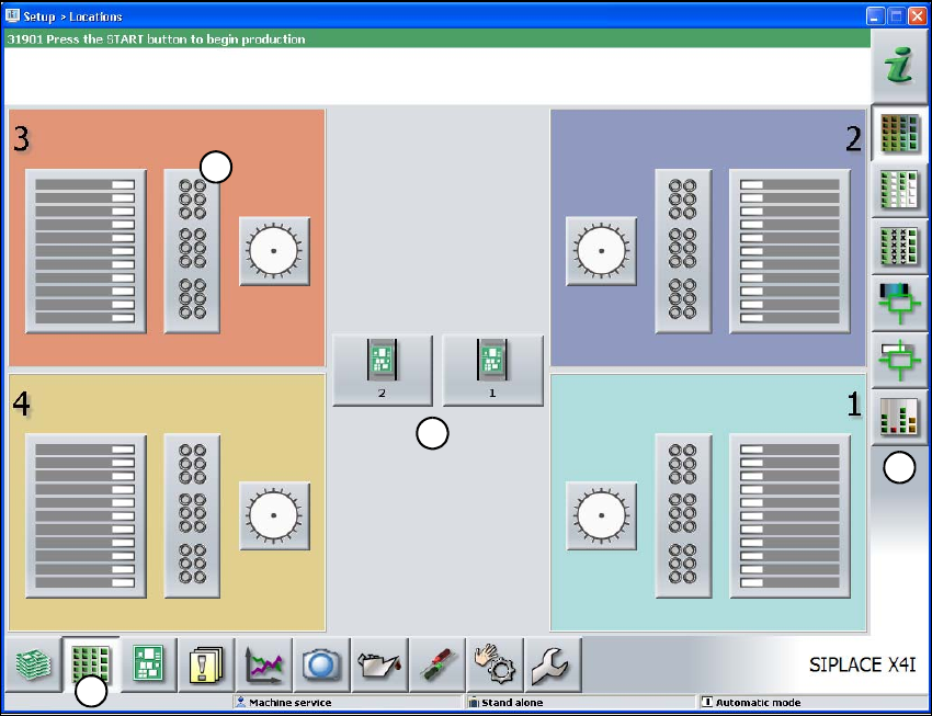
Fig. 5.5 - 3 User interface in the "Feeders, components and nozzles" view (with reference to the SIPLACE X4I)
(1) Toolbar ("Feeders, components and nozzles" button)
(2) Vertical toolbar in the "Feeders, components and nozzles" view.
(3) Processing area with 4 gantries
(4) Button for nozzle change to gantry 3
Click nozzle change from gantry 3 (button 4), for example, to check the nozzle configuration.
1
2
3
4
Tasks on the machine User manual SIPLACE X-series
The user interface From software version SR.70x.xx 01/2011 EN edition
310
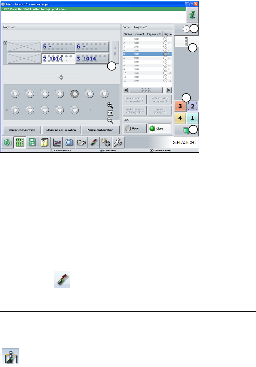
The following view opens:
5
Fig. 5.5 - 4 User interface in the "Nozzle changer" view (with reference to the SIPLACE X4I)
(1) Vertical "Nozzle changer" toolbar
(2) "Nozzle changer" processing area
(3) "Up one level" button for returning to the previous view (in this case the "Feeders, components
and nozzles" view, see previous picture)
(4) Button for switching directly to another gantry
(5) Button for changing directly to the "head configuration"
5.5.5 Settings
The "Settings" view allows you to change various user settings, software options and machine op-
tions.
Click "Settings" on the toolbar.
An additional toolbar appears on the right-hand side. The following table briefly describes the sym-
bols and settings.
1
5
2
3
4
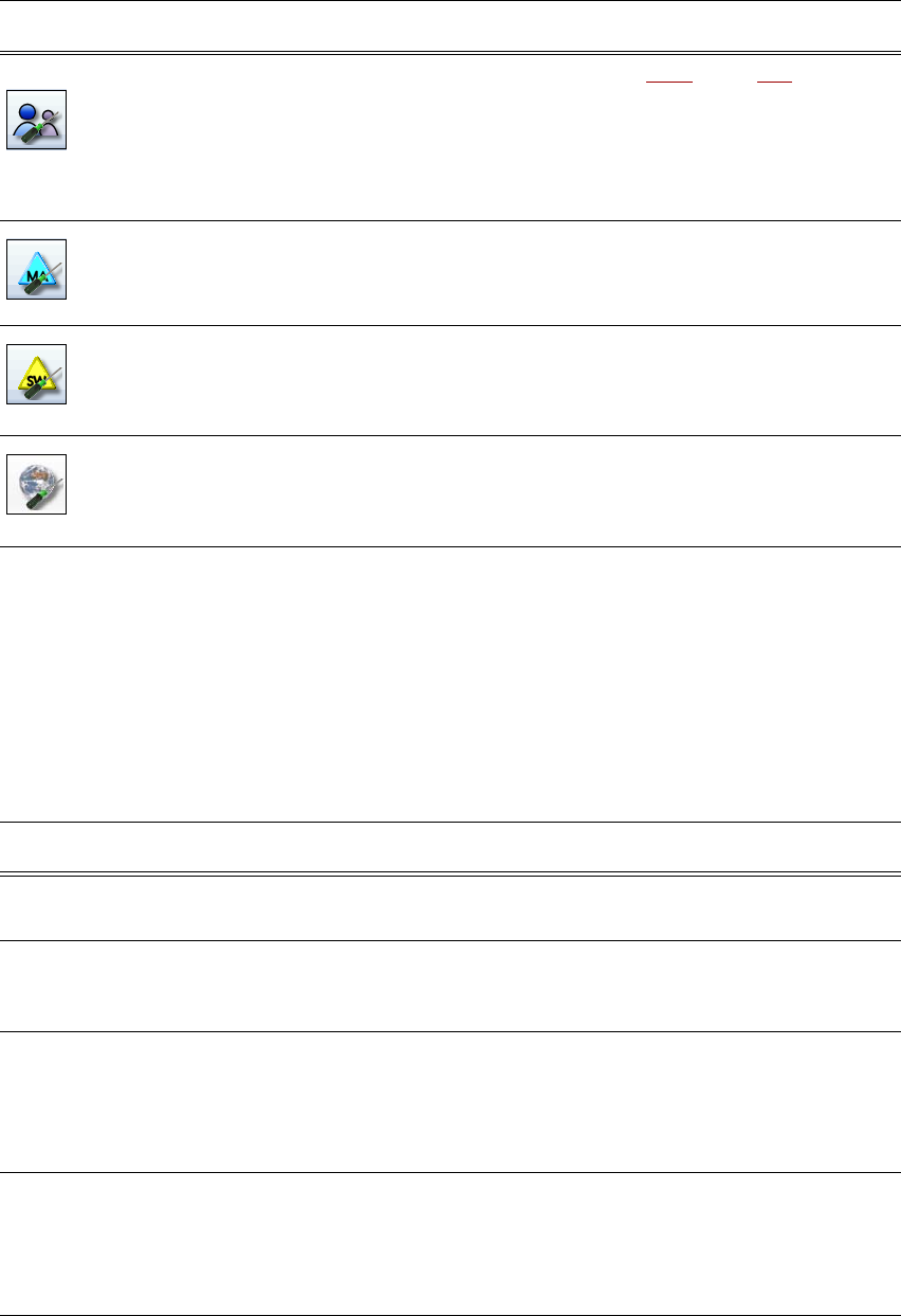
Symbol Settings Description
Machine
settings
For Advanced production, Machine service or SIPLACE service
only.
For setting the control mode and options (e.g. run options).
Shut down machine.
Switch to operating system.
User manual SIPLACE X-series Tasks on the machine
From software version SR.70x.xx 01/2011 EN edition The user interface
311
5.5.6 Application-oriented operation through the use of color marking
On the user interface, symbols, buttons and views can be highlighted in color. The various colors
used immediately show when, for example, intervention by the operator is required or when a
warning has been issued.
The following color markings are used in the station software:
5
User
settings
Setting the operator level (see Section 5.3.3, page 300).
Setting the language. You can choose between "Deutsch" and
"English" as standard. There is also a language CD available for
installing additional languages.
Other options can be set at the "Advanced production" operator
level or above.
Machine options You cannot change any options at the "Basic production" operator
level.
Configure machine options.
Software options For Machine service or SIPLACE service only.
Here you can activate various test functions.
Overview of the
connected exter-
nal systems
Displays all connected external systems (e.g. OIS, SetupCenter).
Displays the connection status and the memory in use. Also used
to clear the connected systems.
Symbol Settings Description
Color Status Meaning
Red Alarm Operator intervention is needed.
In the "Feeders, components and nozzles" view only.
Orange Warning There is a note for the operator.
Immediate operator intervention is not needed, however.
In the "Feeders, components and nozzles" view only.
Green Busy The symbol or button has control of the machine and the status
is OK.
Only available in the "Basic production", "Feeders, compo-
nents and nozzles", "Board", "Check sensors and functions"
and "Service" views.
Green flashing Waiting for board Replaces "Busy" status if the machine is ready in basic pro-
duction mode, but is not actually producing because there is
no board present.
Insert a PCB.
In the "Basic production" view only.