00196504-02_UM_X-Serie_SR70X_EN.pdf - 第321页
User manual SIPLACE X-series Tasks on the machine From software version SR.70x.xx 01/2011 EN edition Changing shift 321 5.8 Changing shif t PLEASE NOTE: 5 Y ou will find additional in formation in the following manuals o…

Tasks on the machine User manual SIPLACE X-series
Indicator lamp status displays From software version SR.70x.xx 01/2011 EN edition
320
5.7.5 Options for combining white and green lamps
5
5.7.6 Response time
Any change in the machine status is displayed at the indicator lamps within three seconds.
A lamp flashes normally Further warning on the side of the indicator lamp.
This also includes warnings from the OIS.
For a component that is made available at several feeder modules
or MTC levels (redundant set-up), this means that:
– At least two feeder modules are empty
– And there are still at least two feeder modules with this
component
Both lamps are flashing Two warnings, one on each side
or
Warning for a module that has not been allocated to a specific side
of the machine.
A lamp is On Alarm on the associated side
Both lamps are On Alarm on both sides.
Or for a component that is not allocated to a specific side.
Or PCB fiducial not found or not detected.
Status Meaning
Status Meaning
Both white lamps flash briefly
Green lamp flashes normally
One of the following operations has just been carried out:
– reference run
– width adjustment
– any other manual function
– calibrate
(Do not open cover during this operation).

User manual SIPLACE X-series Tasks on the machine
From software version SR.70x.xx 01/2011 EN edition Changing shift
321
5.8 Changing shift
PLEASE NOTE: 5
You will find additional information in the following manuals or data media:
– SIPLACE X-series preventive maintenance manual
– Parts catalog on the product CD
5.8.1 Activities at shift change
→ Splice the tapes early. The feeder modules do not have to be refilled as soon as the new shift
starts. This minimizes extended down times.
→ At the shift change, pass important information on to the next operator. This includes, for in-
stance, changes to the placement program. Also read through the list of the descriptions of
the steps to take in Section 5.12
, page 340.
→ Carry out a set-up check.
Make sure that the feeder modules are equipped with the correct components, that they are
at the correct locations in the component trolley and that the conveyor increment is set cor-
rectly.
→ Hand over the line in the same state that you would want to find it in when starting your shift.
This means that:
– The rejection containers are empty.
– The waste tape containers are empty. Follow the safety instructions given in Section
5.8.2
, page 322.
– The feeder areas have been carefully cleaned with a vacuum cleaner.
Tasks on the machine User manual SIPLACE X-series
Changing shift From software version SR.70x.xx 01/2011 EN edition
322
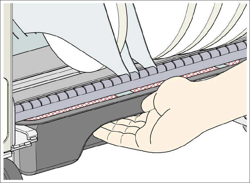
5.8.2 Safety instructions for emptying the waste tape container
5
Fig. 5.8 - 1 Safety instructions for emptying the waste tape container
The waste tape container must be pulled out of the component trolley for emptying. There is a risk
of catching your thumbs as you do so.
→ To avoid this risk, hold the waste tape container with your fingers on the underside of the han-
dle and place your thumb on the handle.
→ Do NOT put your thumbs in the gap between the tape container and waste tape container as
you could catch your thumbs if you do.