00196504-02_UM_X-Serie_SR70X_EN.pdf - 第323页
User manual SIPLACE X-series Tasks on the machine From software version SR.70x.xx 01/2011 EN edi tion Carrying out a walk-through inspection 323 5.9 Carrying out a walk-through inspection 5.9.1 Checking the X feeder modu…
Tasks on the machine User manual SIPLACE X-series
Changing shift From software version SR.70x.xx 01/2011 EN edition
322
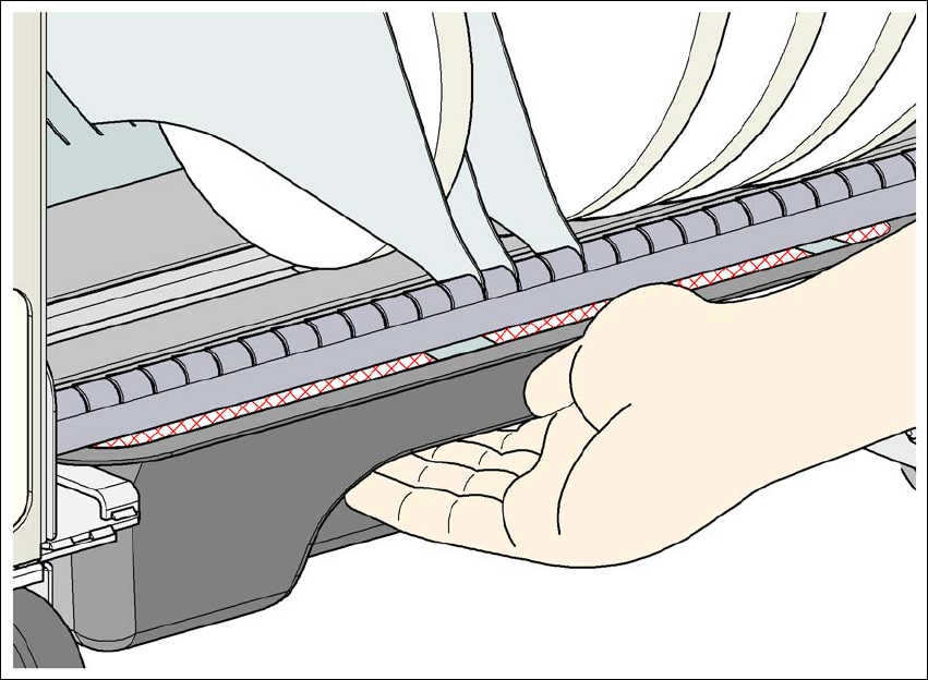
5.8.2 Safety instructions for emptying the waste tape container
5
Fig. 5.8 - 1 Safety instructions for emptying the waste tape container
The waste tape container must be pulled out of the component trolley for emptying. There is a risk
of catching your thumbs as you do so.
→ To avoid this risk, hold the waste tape container with your fingers on the underside of the han-
dle and place your thumb on the handle.
→ Do NOT put your thumbs in the gap between the tape container and waste tape container as
you could catch your thumbs if you do.
User manual SIPLACE X-series Tasks on the machine
From software version SR.70x.xx 01/2011 EN edition Carrying out a walk-through inspection
323
5.9 Carrying out a walk-through inspection
5.9.1 Checking the X feeder modules
5
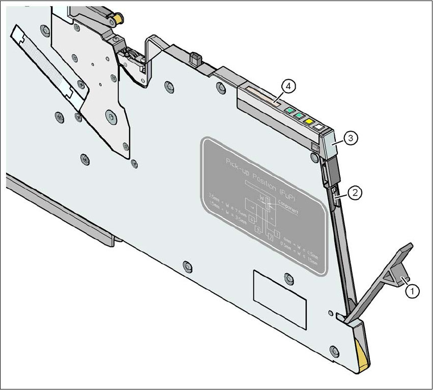
Fig. 5.9 - 1 Checking the X feeder modules
(1) Flap
(2) Blade
(3) Status display
(4) LCD display
5
→ Check to see whether the tape foil removal container for the X tape feeder module is full.
Open the flap (item 1). Pull out the cover foil and cut it with scissors or on the integral blade
(item 2) on 8 and 12 mm X tape feeder modules.

Tasks on the machine User manual SIPLACE X-series
Carrying out a walk-through inspection From software version SR.70x.xx 01/2011 EN edition
324
PLEASE NOTE 5
Never tear the cover foil. This can cause problems with the cover foil pull-off. There is an in-
tegral blade (item 2) for easily cutting the on the 8 and 12 mm X tape feeder modules.
→ Check the multicolor status display (item 3 in Fig. 5.9 - 1
, page 323).
– If it lights up green, the feeder module is on standby.
– If it lights up orange, it is signaling a warning. The text of the warning appears on the LCD
display (item 4 in Fig. 5.9 - 1
, page 323).
– If the status display lights up red, a malfunction has occurred. The text of the warning
appears on the LCD display (item 3 in Fig. 5.9 - 1
, page 323).
A list of the LCD and status displays on the operator panel is given in Section 5.11
, page
337
. 5
If the status display is off, the cause may be as follows: 5
– The feeder module is not in the current set-up.
– The feeder module is defective.
– The feeder module has been disabled (due to a drop in pressure, for example)
5.9.2 Splicing the tapes in good time
PLEASE NOTE:
Splice the tapes early enough so that the feeder modules do not run out of components. Oth-
erwise you will experience prolonged down times.
However, do not splice the tapes too early because if you wind the end of the old tape onto
the new reel after splicing, the reel holding the new tape may become overfilled and the tape
will slip off the reel and become tangled up. This will again result in pick-up errors and pro-
longed down times. 5
5.9.3 Checking the PCB supports
→ Check the position of the magnetic PCB supports on the lifting table:
– Make sure that the PCB supports do not collide with components on the underside of the
PCBs.
– In addition, make sure that the PCB supports do not collide with the PCB conveyor pan-
els.
– Only use PCB supports as described in Section 6.13
, page 420.