00196504-02_UM_X-Serie_SR70X_EN.pdf - 第324页
Tasks on the machine User manual SIPLACE X-series Carrying out a walk-through inspection From software version SR.70x.xx 01/2011 EN edition 324 PLEASE NOTE 5 Never tear the cover foil. This can cause problems with the co…
User manual SIPLACE X-series Tasks on the machine
From software version SR.70x.xx 01/2011 EN edition Carrying out a walk-through inspection
323
5.9 Carrying out a walk-through inspection
5.9.1 Checking the X feeder modules
5
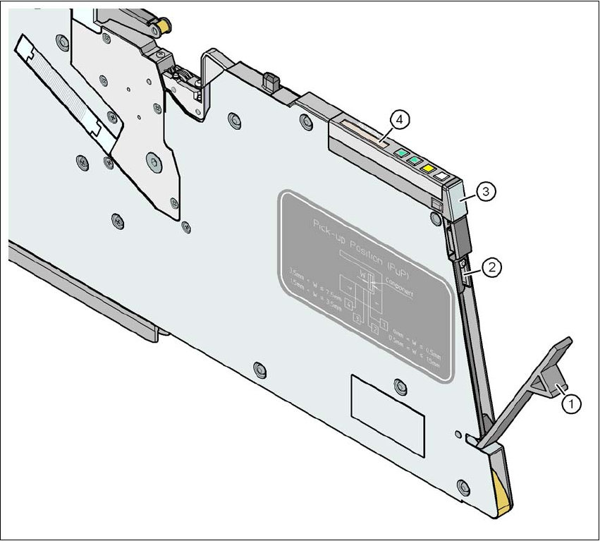
Fig. 5.9 - 1 Checking the X feeder modules
(1) Flap
(2) Blade
(3) Status display
(4) LCD display
5
→ Check to see whether the tape foil removal container for the X tape feeder module is full.
Open the flap (item 1). Pull out the cover foil and cut it with scissors or on the integral blade
(item 2) on 8 and 12 mm X tape feeder modules.

Tasks on the machine User manual SIPLACE X-series
Carrying out a walk-through inspection From software version SR.70x.xx 01/2011 EN edition
324
PLEASE NOTE 5
Never tear the cover foil. This can cause problems with the cover foil pull-off. There is an in-
tegral blade (item 2) for easily cutting the on the 8 and 12 mm X tape feeder modules.
→ Check the multicolor status display (item 3 in Fig. 5.9 - 1
, page 323).
– If it lights up green, the feeder module is on standby.
– If it lights up orange, it is signaling a warning. The text of the warning appears on the LCD
display (item 4 in Fig. 5.9 - 1
, page 323).
– If the status display lights up red, a malfunction has occurred. The text of the warning
appears on the LCD display (item 3 in Fig. 5.9 - 1
, page 323).
A list of the LCD and status displays on the operator panel is given in Section 5.11
, page
337
. 5
If the status display is off, the cause may be as follows: 5
– The feeder module is not in the current set-up.
– The feeder module is defective.
– The feeder module has been disabled (due to a drop in pressure, for example)
5.9.2 Splicing the tapes in good time
PLEASE NOTE:
Splice the tapes early enough so that the feeder modules do not run out of components. Oth-
erwise you will experience prolonged down times.
However, do not splice the tapes too early because if you wind the end of the old tape onto
the new reel after splicing, the reel holding the new tape may become overfilled and the tape
will slip off the reel and become tangled up. This will again result in pick-up errors and pro-
longed down times. 5
5.9.3 Checking the PCB supports
→ Check the position of the magnetic PCB supports on the lifting table:
– Make sure that the PCB supports do not collide with components on the underside of the
PCBs.
– In addition, make sure that the PCB supports do not collide with the PCB conveyor pan-
els.
– Only use PCB supports as described in Section 6.13
, page 420.
User manual SIPLACE X-series Tasks on the machine
From software version SR.70x.xx 01/2011 EN edition Carrying out a walk-through inspection
325
5.9.4 Mount for additional tape reel
5
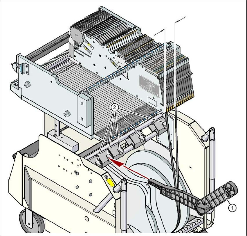
Fig. 5.9 - 2 Mount for additional tape reel
(1) Support for an additional tape reel, item no. 00141217-xx
(2) Mounting device for the support
5
X-series feeder modules can process component tapes without problems if the lateral offset be-
tween the feeder module and the tape reel does not exceed 60 mm. If a predefined set-up means
that the maximum permitted offset cannot be maintained, we recommend that you use the mount
for an additional tape reel (item 1). Simply insert the mount into the holder (item 2) and push it until
the offset is less than the maximum permitted value of 60 mm. The component trolley has 5 hold-
ers in total. Each tape reel mount can hold 2 tape reels, which means that up to ten 15" (381 mm)
reels can be positioned above the tape container.
max. 60 mm