00196504-02_UM_X-Serie_SR70X_EN.pdf - 第336页
Tasks on the machine User manual SIPLACE X-series Setting up the feeder modules From software version SR.70x.xx 01/2011 EN edition 336 5.10.4.5 Splice sensors for X t ape feeder modules S plice sensors can be retrofitted…
User manual SIPLACE X-series Tasks on the machine
From software version SR.70x.xx 01/2011 EN edition Setting up the feeder modules
335
5.10.4.4 Tape support for 8 mm X tape feeder module
5
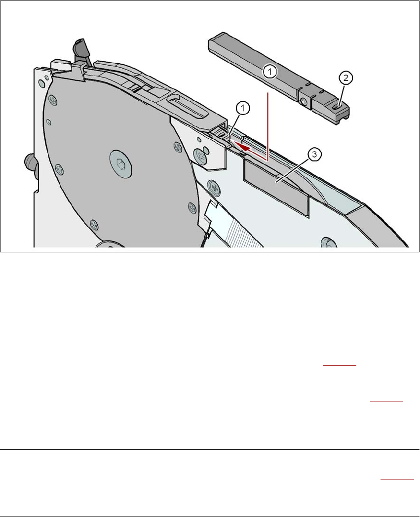
Fig. 5.10 - 8 8 mm X feeder module - tape support and splice sensor
(1) Tape support, removable
(2) Oval opening in the tape support
(3) Splice sensor installation location
The 8 mm X feeder module is equipped with a tape support (item 1 in Fig. 5.10 - 8
). It can easily
be removed if necessary.
→ Insert the tang of a watchmaker's screwdriver into the oval opening (item 2 in Fig. 5.10 - 8
) in
the tape support and pull the tape support out against the direction of travel of the tape.
→ When you insert the tape support, make sure that it engages in its desired position.
PLEASE NOTE 5
For all components size 0402 and smaller, always insert the tape support (item 1 in Fig. 5.10 - 8
)
into the 8 mm X feeder module. This will give you a constant Z pick up height and will minimize
the time needed to correct the pick up heights.

Tasks on the machine User manual SIPLACE X-series
Setting up the feeder modules From software version SR.70x.xx 01/2011 EN edition
336
5.10.4.5 Splice sensors for X tape feeder modules
Splice sensors can be retrofitted to the X tape feeder modules. There are two versions of the sen-
sor:
Splice sensor for 8 mm and 12 mm X tape feeder modules
Splice sensor for 16 mm to 88 mm X tape feeder modules 5
The splice sensor is installed at the position indicated by item 3 in Fig. 5.10 - 8
, page 335.
Tape feeder modules with a splice sensor already installed can also be supplied (see Section
3.9.2
, from page 174).
5.10.5 Setting up the X feeder module
Setting up the X feeder modules is described in the job guide.
User manual SIPLACE X-series Tasks on the machine
From software version SR.70x.xx 01/2011 EN edition Observe LCD and status displays on the X feeder module
337
5.11 Observe LCD and status displays on the X feeder
module
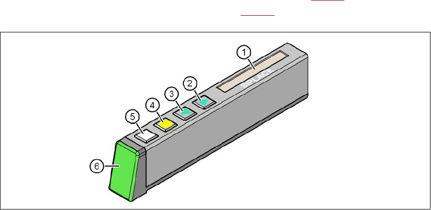
The X feeder modules have a multicolor status display (Pos. 6 in Fig. 5.11 - 1) for signaling the
operating statuses and an LCD display (item 1 in Fig. 5.11 - 1
) to display the texts.
5
Fig. 5.11 - 1 Buttons, LCD and status displays on the X feeder module
(1) LCD display
(2) FORWARD button
(3) BACK button
(4) FOIL button
(5) SET button
(6) Status display, multicolor
5.11.1 Status display
–Green:
The feeder module is on standby and is contained in the current set-up.
– Orange:
A warning is being signalized. The text of the warning appears on the LCD display.
–Red:
A malfunction has occurred. The error message is output on the LCD display.
– OFF:
The feeder module is not contained in the current set-up.