00196504-02_UM_X-Serie_SR70X_EN.pdf - 第365页
User manual SIPLACE X-series Station extensions From software version SR.70x .xx 01/2011 EN edition Nozzle changer 365 6.1.2.2 T echnical dat a 6 6 6 6 6 6.1.2.3 Position of the nozzle changers for the SIPLACE MultiS tar…
Station extensions User manual SIPLACE X-series
Nozzle changer From software version SR.70x.xx 01/2011 EN edition
364
Nozzle magazine for type 28xx nozzles 6
6
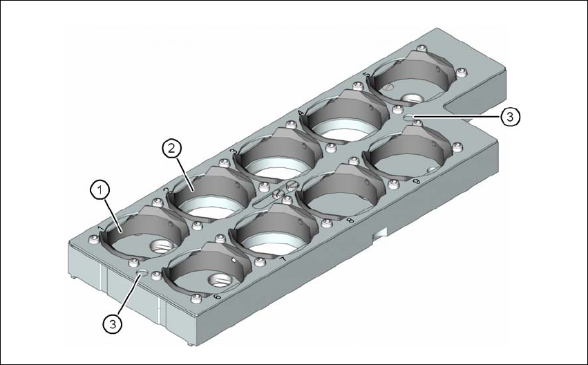
Fig. 6.1 - 12 Nozzle magazine for type 28xx nozzles
(1) 5 holders for 28xx nozzles with a maximum nozzle length of 12.5 mm
(holder numbers 1, 5, 6, 8 and 9)
(2) 4 holders for 28xx nozzles with a maximum nozzle length of 16.5 mm
(holder numbers 2, 3, 4 and 7)
(3) Fiducials (only visible if the locking plate is open)

User manual SIPLACE X-series Station extensions
From software version SR.70x.xx 01/2011 EN edition Nozzle changer
365
6.1.2.2 Technical data
6
6
6
6
6
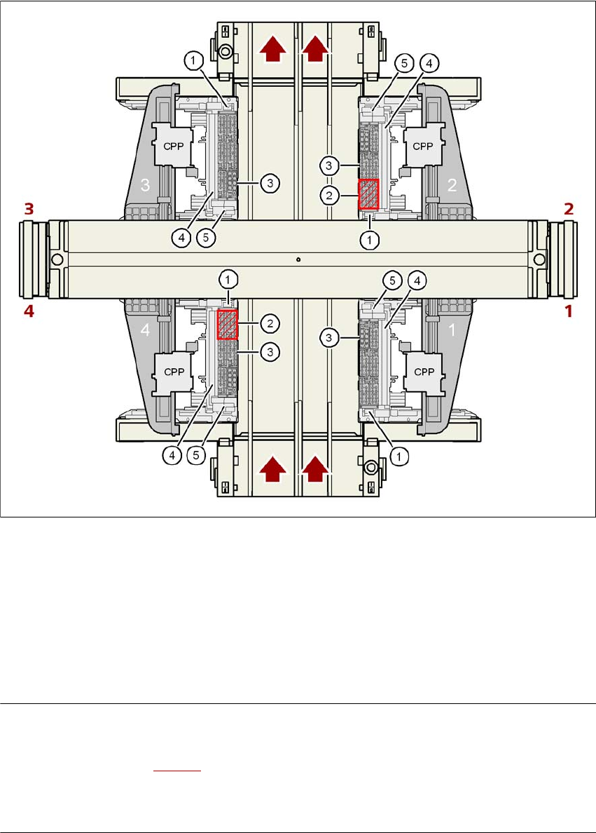
6.1.2.3 Position of the nozzle changers for the SIPLACE MultiStar on the X4I
Nozzle changers may be installed at locations 1, 2, 3 and 4 for the CPP head (item 1 in Fig.
6.1 - 13
, page 366).
This gives the following nozzle changer configuration for the placement machine:
6
Nozzle changer for the SIPLACE MultiStar and SIPLACE SpeedStar
Dimensions (length x width x height) 449 x 94.5 x 55 mm³
Number of nozzle holders
Type 20xx 60
Type 28xx 9
Type 10xx, 11xx, 12xx 72
Nozzle types 20xx (CPP head)
28xx (CPP head)
10xx, 11xx, 12xx (C&P20 head)
Nozzle changeover time approx. 2 s per nozzle
Compressed air connection 0.48 MPa (4.8 bar)
Location
Number of
nozzle magazines
Number of reserve
nozzle magazines
Number of nozzle
holders
1 5 x 20xx + 1 x 28xx - 60 x 20xx, 9 x 28xx
2 4 x 20xx 2 48 x 20xx
3 5 x 20xx + 1 x 28xx - 60 x 20xx, 9 x 28xx
4 4 x 20xx 2 48 x 20xx
Station extensions User manual SIPLACE X-series
Nozzle changer From software version SR.70x.xx 01/2011 EN edition
366
6
6
Fig. 6.1 - 13 Position of the nozzle changers for the SIPLACE MultiStar on the X4I machine
PLEASE NOTE: 6
– At locations 2 and 4, the placement heads are unable to access the two inner nozzle maga-
zines (item 2 in Fig. 6.1 - 13
).
– All magazine locations must be filled since the safety circuit stops the machine in response
to missing magazines or magazines that are not seated correctly.
(1) Nozzle changer
(2) Positions for reserve nozzle magazines (location 2 or 4)
(3) Nozzle magazine
(4) Reject bin for components
(5) Take-off device and reject bin for nozzles