00196504-02_UM_X-Serie_SR70X_EN.pdf - 第383页
User manual SIPLACE X-series Station extensions From software version SR.70x.xx 01/2011 EN edition Dock ing station for the SIPLACE X-series CO tr olley 383 6.2 Docking st ation for the SIPLACE X-series CO trolley Item n…
Station extensions User manual SIPLACE X-series
Nozzle changer From software version SR.70x.xx 01/2011 EN edition
382
– grippers that grip the component at its outer edges and
– grippers that grip the component at its inner edge.
Information on special nozzles and grippers is available from ASM AS. For the production of spe-
cial magazines and grippers, again contact ASM AS.
User manual SIPLACE X-series Station extensions
From software version SR.70x.xx 01/2011 EN edition Docking station for the SIPLACE X-series CO trolley
383
6.2 Docking station for the SIPLACE X-series CO trolley
Item no. 00116933-xx Docking station for the SIPLACE X component trolley
6.2.1 Description
The docking station is an additional component for the set-up area. It forms the link between the
set-up area and the component trolley for the SIPLACE X-series. The docking station allows the
component trolleys to be set up with feeder modules and function tests and set-up checks to be
carried out externally.
6
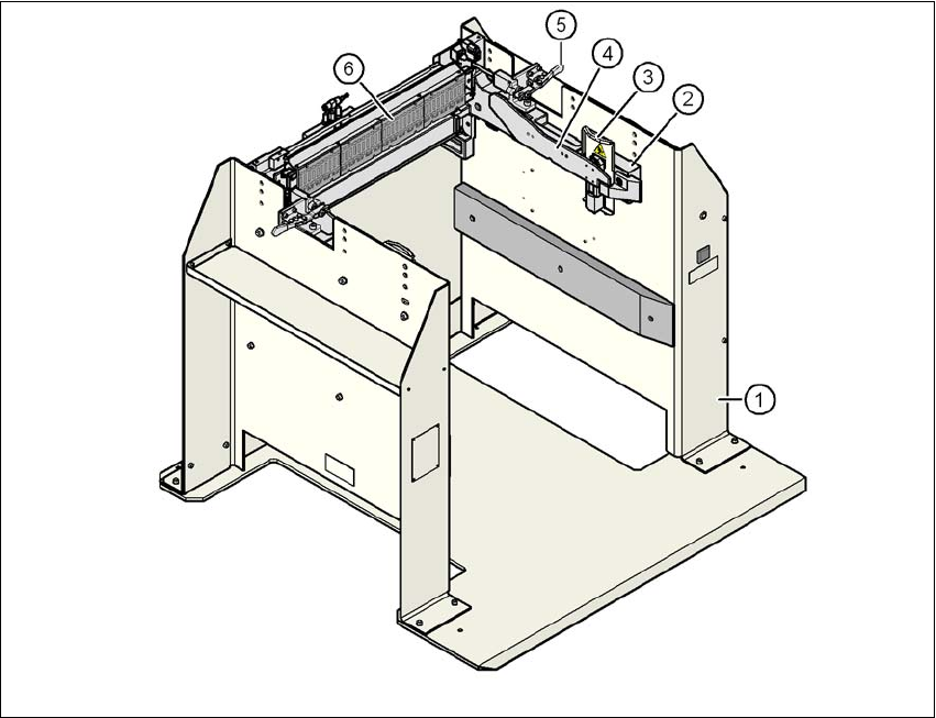
Fig. 6.2 - 1 Docking station, SIPLACE X-series
(1) Docking station
(2) Component trolley docking unit, X-series
(3) Guard plate with warning label W204
(4) Rails for guiding and docking in the component table
(5) Horizontal tensioner for locking the component trolley
(6) EDIF (energy and data interface)

Station extensions User manual SIPLACE X-series
Docking station for the SIPLACE X-series CO trolley From software version SR.70x.xx 01/2011 EN edition
384
The basic tasks of the docking station are as follows:
– Supplying the component trolley and X feeder modules with power
– Supplying the component trolley and X feeder modules with compressed air
– Providing an infrastructure for communication between the PC at the set-up area and the
feeder modules
The operator can use the docking station to carry out function tests on the X feeder modules and
check the set-up outside the production environment. Two rows, each with four docking stations,
are connected via the CAN bus of the initial set-up PC. Each docking station has a separate power
and compressed air connection.
The component trolley docking unit (item 2 in Fig. 6.2 - 1
, page 383) of the docking station can be
adapted to the desired PCB conveyor height. For the initial set-up, the component trolley is
pushed into the docking station (item 1 in Fig. 6.2 - 1
, page 383). The component trolley slides on
the rails of the component trolley docking unit, using the roller bearings attached to the sides of
the component trolley, to the energy and data interface connection. The component table is opti-
mally positioned in the process with the EDIF of the feeder modules to the EDIF (item 5 in Fig. 6.2
- 1, page 383) of the component trolley docking unit and fixed in this position with both horizontal
tensioners. The guard plates (item 3 in Fig. 6.2 - 1
, page 383) prevent access to the castors on
the component trolley if this is pushed into the docking station.
6
Key to fig. 6.2 - 2, page 385
(1) Compressed air connection
(2) CAN bus connection
(3) Power supply connection