00196504-02_UM_X-Serie_SR70X_EN.pdf - 第385页
User manual SIPLACE X-series Station extensions From software version SR.70x.xx 01/2011 EN edition Dock ing station for the SIPLACE X-series CO tr olley 385 6 Fig. 6.2 - 2 Docking station - Dimensi ons in millimeters, co…

Station extensions User manual SIPLACE X-series
Docking station for the SIPLACE X-series CO trolley From software version SR.70x.xx 01/2011 EN edition
384
The basic tasks of the docking station are as follows:
– Supplying the component trolley and X feeder modules with power
– Supplying the component trolley and X feeder modules with compressed air
– Providing an infrastructure for communication between the PC at the set-up area and the
feeder modules
The operator can use the docking station to carry out function tests on the X feeder modules and
check the set-up outside the production environment. Two rows, each with four docking stations,
are connected via the CAN bus of the initial set-up PC. Each docking station has a separate power
and compressed air connection.
The component trolley docking unit (item 2 in Fig. 6.2 - 1
, page 383) of the docking station can be
adapted to the desired PCB conveyor height. For the initial set-up, the component trolley is
pushed into the docking station (item 1 in Fig. 6.2 - 1
, page 383). The component trolley slides on
the rails of the component trolley docking unit, using the roller bearings attached to the sides of
the component trolley, to the energy and data interface connection. The component table is opti-
mally positioned in the process with the EDIF of the feeder modules to the EDIF (item 5 in Fig. 6.2
- 1, page 383) of the component trolley docking unit and fixed in this position with both horizontal
tensioners. The guard plates (item 3 in Fig. 6.2 - 1
, page 383) prevent access to the castors on
the component trolley if this is pushed into the docking station.
6
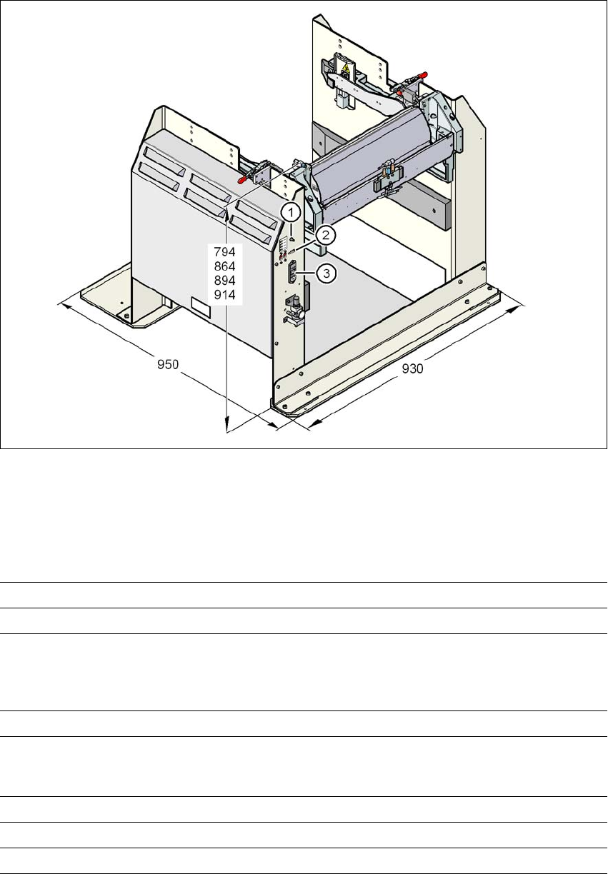
Key to fig. 6.2 - 2, page 385
(1) Compressed air connection
(2) CAN bus connection
(3) Power supply connection
User manual SIPLACE X-series Station extensions
From software version SR.70x.xx 01/2011 EN edition Docking station for the SIPLACE X-series CO trolley
385
6
Fig. 6.2 - 2 Docking station - Dimensions in millimeters, connection points
6.2.2 Technical data
6
Dimensions
Length x width 950 mm x 930 mm
Height 794 mm for 830 mm PCB conveyor height
864 mm for 900 mm PCB conveyor height
894 mm for 930 mm PCB conveyor height
914 mm for 950 mm PCB conveyor height
Weight 120 kg
Compressed air pressure values
p
min
p
max
0.5 MPa (5.0 bar)
1.0 MPa (10.0 bar)
Compressed air connection coupler plug KS 2-M5-A
Compressed air consumption 50 Nl/min
a
Supply voltage 88 - 264 VAC
Station extensions User manual SIPLACE X-series
Docking station for the SIPLACE X-series CO trolley From software version SR.70x.xx 01/2011 EN edition
386
6
6
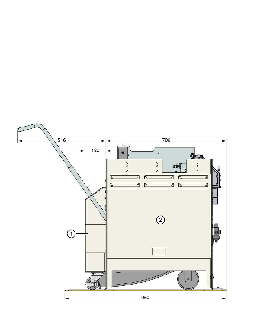
6.2.3 Dimensions for the docking station with component trolley docked
6
Fig. 6.2 - 3 Docking station with component trolley docked - dimensions in millimeters
(1) CO trolley
(2) Docking station
Rated current 3.5 A (230 VAC)
7 A (115 VAC)
Nominal apparent power 0.8 kW
Fuse protection 2 x 8 A
a) Under normal atmospheric conditions at 20°C and 1013 hPa