00196504-02_UM_X-Serie_SR70X_EN.pdf - 第389页
User manual SIPLACE X-series Station extensions From software version SR.70x.xx 01/2011 EN edition Dock ing station for the SIPLACE X-series CO tr olley 389 6.2.5 Adapting the docking st atio n to the PCB conveyor height…

Station extensions User manual SIPLACE X-series
Docking station for the SIPLACE X-series CO trolley From software version SR.70x.xx 01/2011 EN edition
388
Key to fig. 6.2 - 4
, page 387.
(1) Main power supply indicator lamp
(2) Button for locking and releasing all the feeder modules on the component trolley
(3) Horizontal tensioner for fixing the component table lever in the "closed" position
(4) Label showing switches S1 and S2 for CAN bus addressing
(5) Switches S1 and S2 for setting the CAN bus address
(6) Power switch
(7) Rotary knob for setting the operating pressure
(8) Manometer for displaying the operating pressure
User manual SIPLACE X-series Station extensions
From software version SR.70x.xx 01/2011 EN edition Docking station for the SIPLACE X-series CO trolley
389
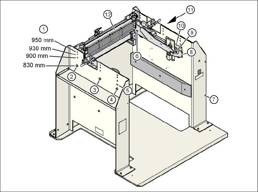
6.2.5 Adapting the docking station to the PCB conveyor height
The component trolley docking unit can be adjusted to PCB conveyor heights of 830 mm, 900 mm,
930 mm and 950 mm in just a few simple actions.
6
Fig. 6.2 - 5 Adapting the component trolley docking unit to the PCB conveyor heights
(1) Holes for the PCB conveyor height
(2) Hexagonal nut M8 and washer, 2x
(3) Hexagonal nut M8 and washer, 2x
(4) Hexagonal nut M8 and washer, 2x
(5) Slot for height adjustment
(6) Hexagon socket head screw M8x40, 6x
(7) Hexagon socket head screw M5x12, 4x
(8) Guide
(9) Hexagon socket head screw M8x18, 2x
(10) Side section, component trolley docking unit
(11) Paneling on the docking station
(12) Feeder module control unit (FCU)
Station extensions User manual SIPLACE X-series
Docking station for the SIPLACE X-series CO trolley From software version SR.70x.xx 01/2011 EN edition
390
6.2.5.1 Tools
You will need the following tools and equipment to adjust the height for the component trolley
docking unit:
– Allen key, set
– Fork wrench, size 13
6.2.5.2 Converting the CO trolley docking unit to other heights
WARNING 6
→ Disconnect the docking station from the main power supply.
→ Disconnect the docking station from the compressed air supply
The weight of the component trolley docking unit is approx. 40 kg.
→ Please ask a second person to help you with the conversion if necessary.
→ Note the order of the steps described.
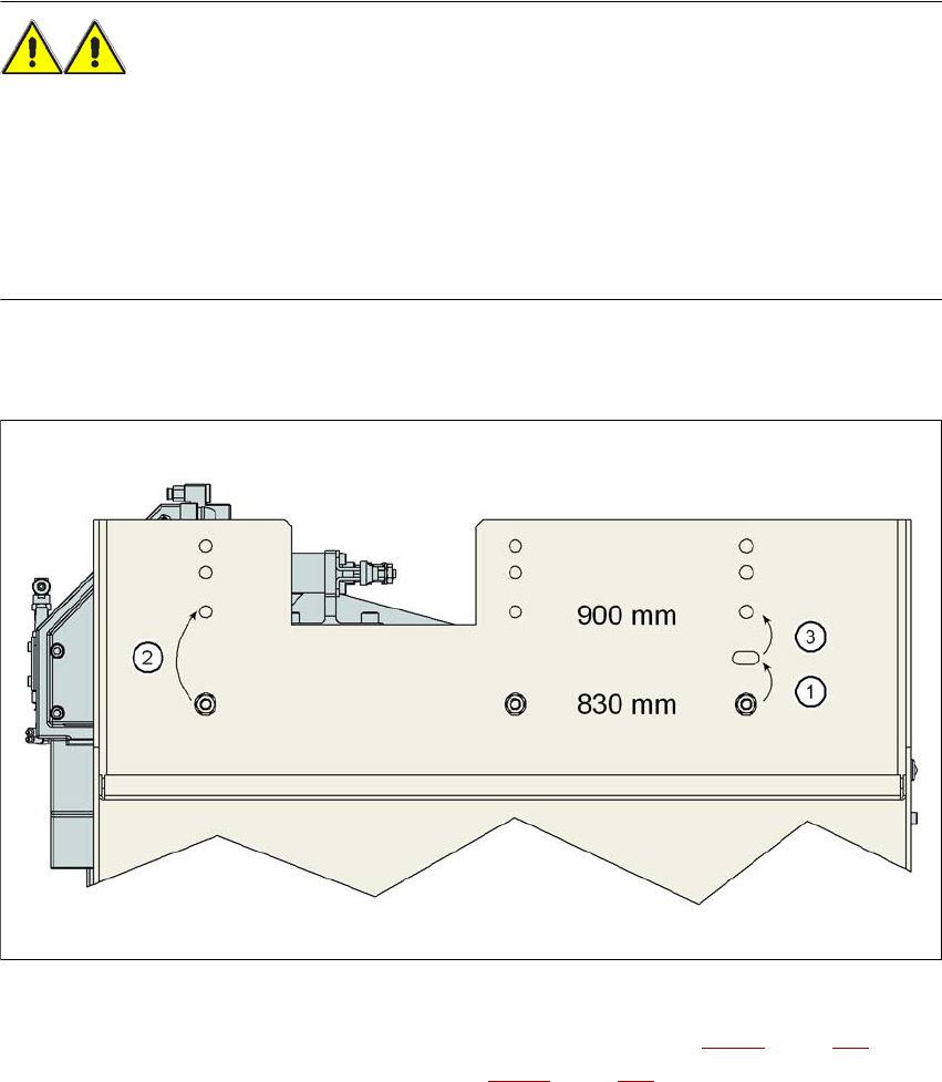
6.2.5.3 Converting the CO trolley docking unit to a height of 830 mm or 900 mm
6
Fig. 6.2 - 6 Steps for conversion from a height of 830 mm to a height of 900 mm
→ Remove the two hexagon socket head screws M8x18 (item 9 in Fig. 6.2 - 5, page 389) and
remove the left and right guides (item 8 in Fig. 6.2 - 5
, page 389).