00196504-02_UM_X-Serie_SR70X_EN.pdf - 第391页
User manual SIPLACE X-series Station extensions From software version SR.70x.xx 01/2011 EN edition Dock ing station for the SIPLACE X-series CO tr olley 391 6 PLEASE NOTE: 6 Only remove the pane l (item 9 in Fig. 6.2 - 5…
Station extensions User manual SIPLACE X-series
Docking station for the SIPLACE X-series CO trolley From software version SR.70x.xx 01/2011 EN edition
390
6.2.5.1 Tools
You will need the following tools and equipment to adjust the height for the component trolley
docking unit:
– Allen key, set
– Fork wrench, size 13
6.2.5.2 Converting the CO trolley docking unit to other heights
WARNING 6
→ Disconnect the docking station from the main power supply.
→ Disconnect the docking station from the compressed air supply
The weight of the component trolley docking unit is approx. 40 kg.
→ Please ask a second person to help you with the conversion if necessary.
→ Note the order of the steps described.
6.2.5.3 Converting the CO trolley docking unit to a height of 830 mm or 900 mm
6
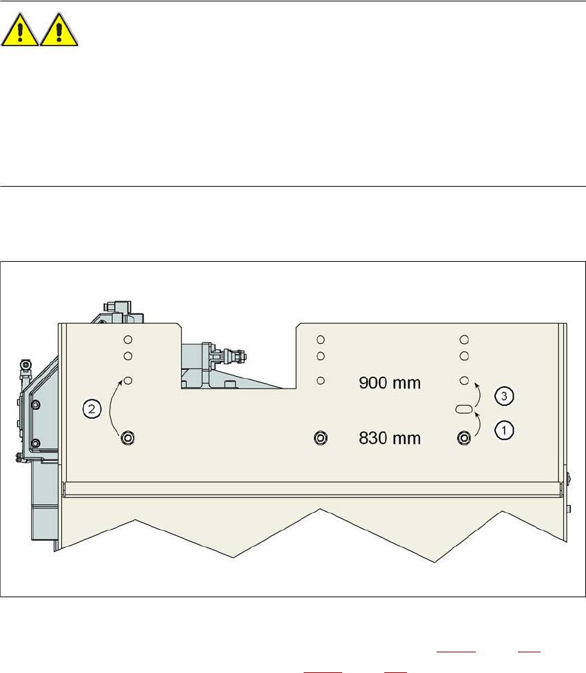
Fig. 6.2 - 6 Steps for conversion from a height of 830 mm to a height of 900 mm
→ Remove the two hexagon socket head screws M8x18 (item 9 in Fig. 6.2 - 5, page 389) and
remove the left and right guides (item 8 in Fig. 6.2 - 5
, page 389).
User manual SIPLACE X-series Station extensions
From software version SR.70x.xx 01/2011 EN edition Docking station for the SIPLACE X-series CO trolley
391
6
PLEASE NOTE: 6
Only remove the panel (item 9 in Fig. 6.2 - 5
, page 389) in the following situations:
– You are converting the component trolley docking unit to a height of 830 mm.
– You are converting the component trolley docking unit height of 830 mm to another height.
→ Remove the 4 hexagon socket head screws M5x12 (item 7 in Fig. 6.2 - 5
, page 389). Hold the
panel tightly so that it does not drop down.
→ Remove the panel.
CAUTION 6
Be careful not to damage any cables while raising and lowering the component trolley docking
unit.
→ Release both screw connections (item 3 in Fig. 6.2 - 5
, page 389).
→ Loosen both screw connections (item 2 in Fig. 6.2 - 5
, page 389).
→ Remove both M8 hexagonal nuts and washers (item 4 in Fig. 6.2 - 5
, page 389).
→ Hold the component trolley docking unit firmly by the side panel (item 10 in Fig. 6.2 - 5
, page
389
) while you remove the two hexagon socket head screws M8x40 at this point.
→ Swivel the component trolley docking unit upwards until the hole in the side section is covered
with the slot (item 5 in Fig. 6.2 - 5
, page 389).
→ Fasten the side section at this location. Only hand-tighten the nuts.
→ Hold the component trolley docking unit firmly by the FCU (item 12 in Fig. 6.2 - 5
, page 389)
while you remove the screwed connections at item 2 in Fig. 6.2 - 5
, page 389.
→ Swivel the component trolley docking unit upwards until the hole in the side section is covered
with the 900 mm hole (item 1 in Fig. 6.2 - 5
, page 389).
→ Fasten the side section at this location. Only hand-tighten the nuts.
→ Swivel the component trolley docking unit from the slot (item 5 in Fig. 6.2 - 5
, page 389 to the
900 mm hole upwards and fixed in place firmly at this location.
→ Check all screw connections at items 2, 3 and 4 in the 900 mm component trolley height for
firm seating.
→ Fix the left and right guides (item 8 in Fig. 6.2 - 5
, page 389) using the hexagon socket head
screw M8x18 (item 9 in Fig. 6.2 - 5
, page 389).
→ Fix the panel (item 11 in Fig. 6.2 - 5
, page 389) using the 4 hexagon socket head screw M5x12
(item 7 in Fig. 6.2 - 5
, page 389) .
Station extensions User manual SIPLACE X-series
Docking station for the SIPLACE X-series CO trolley From software version SR.70x.xx 01/2011 EN edition
392
PLEASE NOTE 6
Reverse the sequence to convert from a height of 900 mm to 830 mm (see Fig. 6.2 - 6
, page
390).
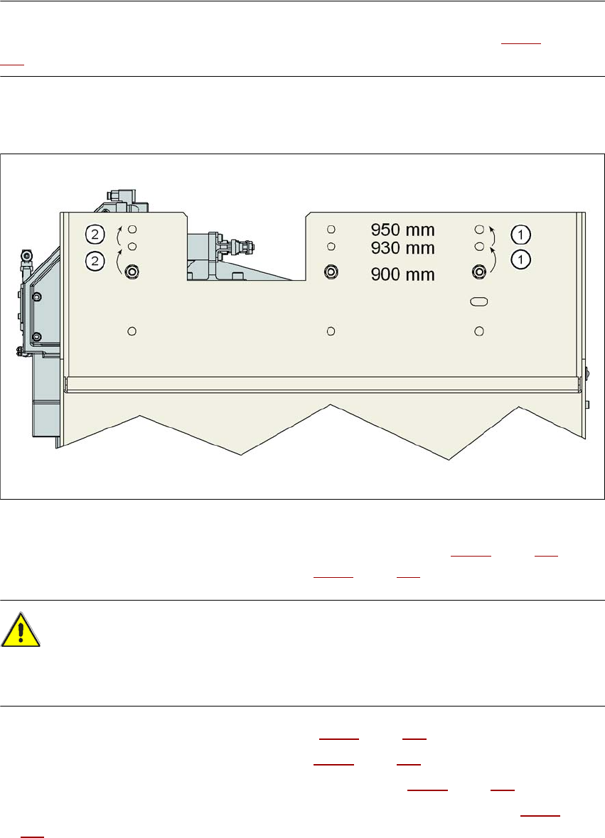
6.2.5.4 Converting the CO trolley docking unit to a height of 900, 930 or 950 mm
6
Fig. 6.2 - 7 Steps for conversion from a height of 830 mm to a height of 900 mm
→ Remove the two hexagon socket head screws M8x18 (item 9 in Fig. 6.2 - 5, page 389) and
remove the left and right guides (item 8 in Fig. 6.2 - 5
, page 389).
CAUTION 6
Be careful not to damage any cables while raising and lowering the component trolley docking
unit.
→ Release both screw connections (item 3 in Fig. 6.2 - 5, page 389).
→ Loosen both screw connections (item 2 in Fig. 6.2 - 5
, page 389).
→ Remove both M8 hexagonal nuts and washers (item 4 in Fig. 6.2 - 5
, page 389).
→ Hold the component trolley docking unit firmly by the side panel (item 10 in Fig. 6.2 - 5
, page
389
) while you remove the two hexagon socket head screws M8x40 at this point.
→ Swivel the component trolley docking unit to the next highest position.
→ Fasten the side section at this location. Only hand-tighten the nuts.