00196504-02_UM_X-Serie_SR70X_EN.pdf - 第409页
User manual SIPLACE X-series Station extensions From software version SR.70x.xx 01/2011 EN editi on Multicolor PCB camera, type 24, digital 409 6 6 6 6 6 6.8 Multicolor PCB camera, type 24, digit al 6.8.1 Structure Item …
Station extensions User manual SIPLACE X-series
Component camera for the MultiStar From software version SR.70x.xx 01/2011 EN edition
408
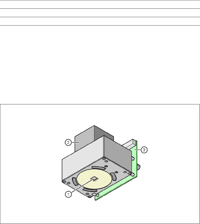
6.7.2 C&P component camera, type 38, 16 x 16, digital
Item no. 00119783-xx 01005 camera for the CPP head
6.7.2.1 Description
We recommend that you install this component camera on the CPP head in place of the type 30
component camera if the CPP head is to be used to mass produce PCBs with 01005 components.
6.7.2.2 Structure
6
Fig. 6.7 - 2 C&P component camera, type 38, 16 x 16, digital
(1) Component camera lens and illumination
(2) Camera amplifier
(3) Illumination control
6.7.2.3 Technical data
6
Component dimensions 0.18 x 0.18 mm² to 16 x 16 mm²
Range of components 01005 to 16 x 16 mm²
Min. lead pitch 0.25 mm
Min. lead width 0.1 mm
Min. ball pitch 0.25 mm
User manual SIPLACE X-series Station extensions
From software version SR.70x.xx 01/2011 EN edition Multicolor PCB camera, type 24, digital
409
6
6
6
6
6
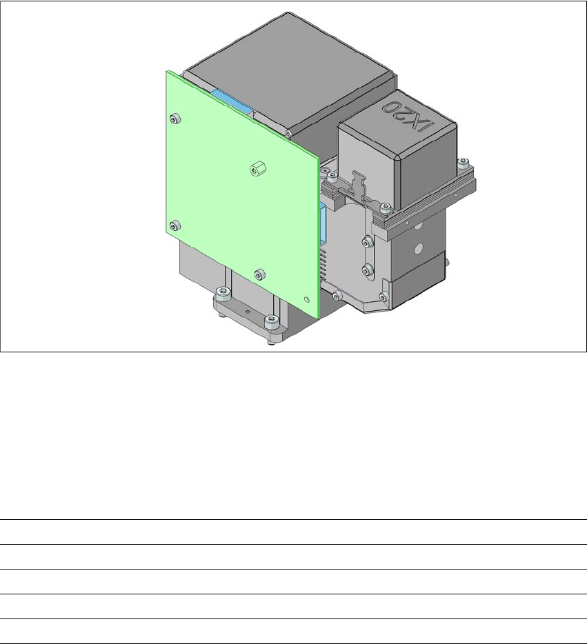
6.8 Multicolor PCB camera, type 24, digital
6.8.1 Structure
Item no. 00119774-xx PCB camera, X-series, multicolor, type 24
6
Fig. 6.8 - 1 Multicolor PCB camera, type 24, digital
(1) PCB camera lens and illumination
(2) Camera amplifier
(3) Illumination control
6
Min. ball diameter 0.14 mm
Field of vision 20.5 x 20.5 mm²
Method of illumination front-illumination (5 levels, programmable as required)

Station extensions User manual SIPLACE X-series
Multicolor PCB camera, type 24, digital From software version SR.70x.xx 01/2011 EN edition
410
6.8.2 Technical data
6
6.8.3 Illumination methods
The following illumination methods may be selected on the multicolor PCB camera:
– White lighting
This method of illumination is used for standard PCBs with tinned fiducials.
– Blue oblique lighting
This generally allows a considerable improvement in the contrast to be achieved with bright
fiducials on a light base material, such as ceramic or CEM. Even fiducials that are covered
with solder resist can be better detected on a light background.
– Infrared lighting
This method of illumination is particularly useful for fiducials that are covered with solder re-
sist, or for fiducials on flex material. It may even be possible to improve detection for silver/
platinum fiducials on ceramic; this should be determined in advance with a trial centering/
placement process.
6.8.4 Fiducials and ink spot criteria
Fiducials and ink spot criteria can be found in Sections 3.8.6 and 3.8.7, page 168.
Field of vision 5.7 x 5.7 mm²
Distance from the focus plane 28 mm
Method of illumination front-illumination (5 levels, programmable as required)
Fiducial size 0.3 mm to 2.5 mm edge length for a PCB conveyor tolerance of
± 1.0 mm
up to 3.0 mm edge length for a PCB conveyor tolerance of < 1.0
mm
Bad fiducial size 0.3 mm to 3.0 mm edge length