00196504-02_UM_X-Serie_SR70X_EN.pdf - 第61页
User manual SIPLACE X-series Operational safety From software version SR.70x.xx 01/ 2011 EN edition Laser classification 61 2.3.3 Laser class 2 The following modules are assi gned to laser class 2: – Laser light barrier …
Operational safety User manual SIPLACE X-series
Laser classification From software version SR.70x.xx 01/2011 EN edition
60
2.3 Laser classification
2.3.1 Laser class 1
2.3.1.1 Classification of the whole machine
2
PLEASE NOTE: 2
Modules in laser classes 1 and 1M are not identified.
2.3.1.2 Classification of the camera systems
2
2.3.2 Laser class 1M
Do not look directly at this with optical instruments!
2
2
All installed camera systems and the whole machine when ready
for operation are assigned to laser class 1.
The laser classes are determined according to DIN EN 60825-
1:2001
2
The following camera systems are assigned to laser class 1:
– PCB camera, type 34, digital
– Multicolor PCB camera, type 24, digital
– Component cameras for the SIPLACE TwinStar
Stationary P&P component camera, type 33, 55 x 45, digital
Stationary P&P component camera, type 25, 16 x 16, digital
2
The following camera systems are assigned to laser class 1M:
– C&P component camera, type 23, 6 x 6 on the SpeedStar
– C&P component camera, type 30, 27 x 27 on the MultiStar

User manual SIPLACE X-series Operational safety
From software version SR.70x.xx 01/2011 EN edition Laser classification
61
2.3.3 Laser class 2
The following modules are assigned to laser class 2:
– Laser light barrier, placement area 1 in the PCB conveyor
– Laser light barrier, placement area 2 in the PCB conveyor
– PCB barcode scanner
– Component sensor on the SpeedStar
– Component sensor on the MultiStar
2
2.3.4 Laser class 3B
The 3D coplanarity sensor is assigned to laser class 3B.
2
PLEASE NOTE: 2
The entire machine is classified as laser class 2 if the coplanarity 3D laser module option is
installed.
2
Laser radiation
Do not look into beam!
2
Laser radiation
Do not expose to beam!
2
Laser radiation
Do not look into beam!
Operational safety User manual SIPLACE X-series
Safety instructions for transporting the machine From software version SR.70x.xx 01/2011 EN edition
62
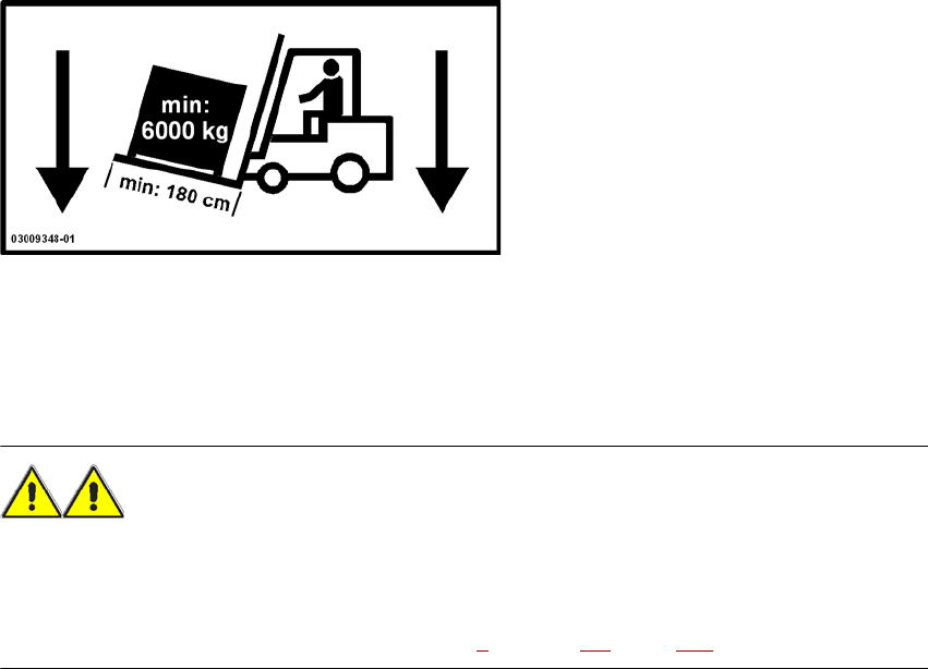
2.4 Safety instructions for transporting the machine
2
Use a fork-lift truck with the following specification to carry the machine:
Fork length: min. 1800 mm
Carrying power: min. 6000 kg
Clear width between forks: min. 350 mm 2
WARNING
RISK OF TIPPING 2
If the required specification cannot be applied to the fork-lift, there is a risk that the fork-lift will tip
over when carrying the machine.
Transporting the machine is described in chapter 4, Section 4.1, page 209.