00196504-02_UM_X-Serie_SR70X_EN.pdf - 第68页
Operational safety User manual SIPLACE X-se ries Safety instructions for operating the mach ine F rom software version SR.70x.xx 01/2011 EN edition 68 The assemb ly positions fo r all placeme nt machines fr om the SIPLAC…
User manual SIPLACE X-series Operational safety
From software version SR.70x.xx 01/2011 EN edition Safety instructions for operating the machine
67
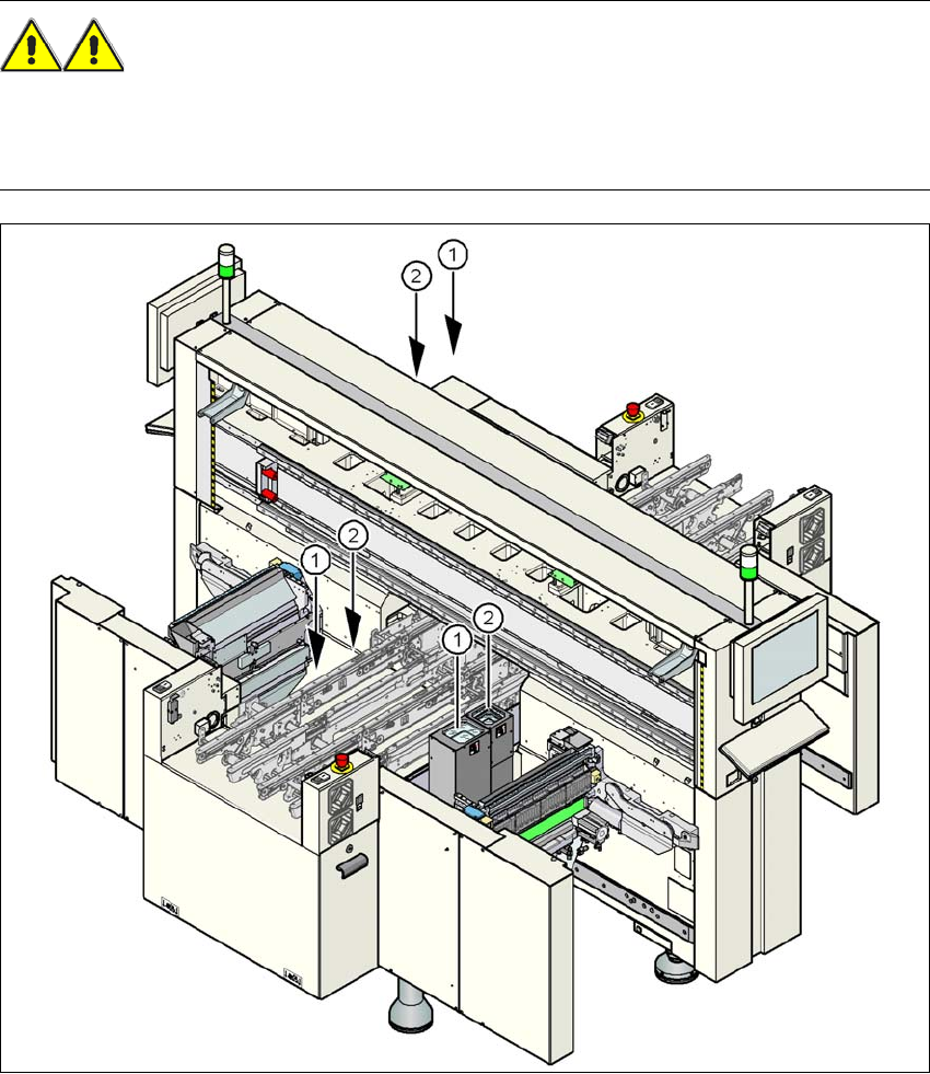
2.5.4 Safety instructions for the TwinStar component cameras during
a placement head change
WARNING 2
When the placement head is changed from the TwinStar to the SpeedStar, the TwinStar's com-
ponent cameras (stationary, P&P, type 33, 55 x 45, and type 25, 16 x 16) must be removed, oth-
erwise the SpeedStar will collide with the camera housings.
2
Fig. 2.5 - 3 Safety instructions for the TwinStar vision modules during a placement head change
(1) Assembly position for the component camera (stationary, P&P, type 33, 55 x 45) with refer-
ence to the X3
(2) Assembly position for the component camera (stationary, P&P, type 25, 16 x 16) with refer-
ence to the X3
Operational safety User manual SIPLACE X-series
Safety instructions for operating the machine From software version SR.70x.xx 01/2011 EN edition
68
The assembly positions for all placement machines from the SIPLACE X-series are shown in
Section 3.8.2
, from page 162. 2
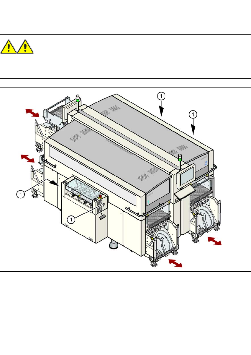
2.5.5 Safety instructions for docking the component trolley in or out
WARNING
To prevent accidents (risk of crushing), the component trolley may only be docked in or out by
one person.
2
Fig. 2.5 - 4 Buttons on the input and output side for docking the component trolley in or out
2
(1) Buttons on the input and output side for docking the component trolley in or out
2
The safety concept for the component trolley change requires the operator to press a button (item
1) on the input or output side of the machine in order to dock the component trolley in or out. This
ensures that the operator is always standing to the side of the machine. In addition, the component
trolley can only be docked in if the protective covers are closed.
Docking the component trolley in or out is described in Section 5.15
, page 344. Follow the instruc-
tions exactly as described in this section.

User manual SIPLACE X-series Operational safety
From software version SR.70x.xx 01/2011 EN edition Safety instructions for operating the machine
69
2.5.6 Note on the ESD safety of the machines
Only use nozzles that are identified as conductive. This is the only way to meet the requirements
for the ESD safety of the machine.
2.5.7 Safety instructions for emptying the waste tape container
The waste tape container must be pulled out of the component trolley for emptying. There is a risk
of catching your thumbs as you do so. Please observe the safety instructions given in Section
5.8.2
, page 322 to prevent this from happening.
2.5.8 Safety instructions for correct use of the reject bin
Observe the following instructions to avoid risk of collision between the placement head and com-
ponent or the nozzle reject bin:
→ Make sure, that the reject bin is seated correctly in its mount.
→ Check that the reject bin does not project over the mount.
PLEASE NOTE 2
For every reject bin, a sensor (see Section 6.4
, page 403) can be retrofitted which signalizes the
correct position of the reject bin.