00196504-02_UM_X-Serie_SR70X_EN.pdf - 第75页
User manual SIPLACE X-series Operational safety From software version SR.70x.xx 01/2011 EN edition Safety equipment 75 2 Fig. 2.6 - 4 Position of switches and buttons - View of the PCB input side (1) Emergency stop butto…
Operational safety User manual SIPLACE X-series
Safety equipment From software version SR.70x.xx 01/2011 EN edition
74
2.6.2 Switches and buttons on the machine
2.6.2.1 Position of switches and buttons on the machine
2
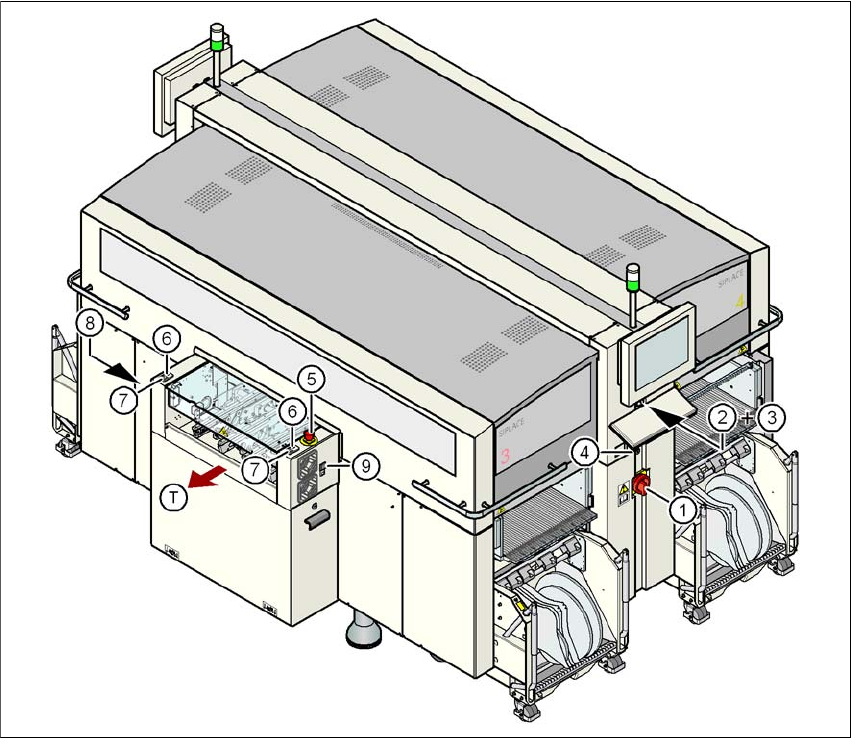
Fig. 2.6 - 3 Position of switches and buttons - View of the PCB output side
(1) Main power switch
(2) Stop button (black) on the operator panel on the power supply side
(3) Start button (white) on the operator panel on the power supply side
(4) Component counter on the operator panel on the power supply side
(5) Emergency stop button on the output side
(6) Start button (white) on the output side
(7) Stop button (black) on the output side
(8) Button (black) for docking the component trolley in or out, location 2
(9) Button (black) for docking the component trolley in or out, location 3
(T) PCB transport direction
User manual SIPLACE X-series Operational safety
From software version SR.70x.xx 01/2011 EN edition Safety equipment
75
2
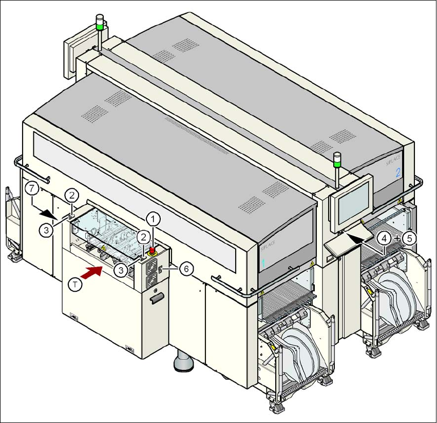
Fig. 2.6 - 4 Position of switches and buttons - View of the PCB input side
(1) Emergency stop button on the input side
(2) Start button (white) on the input side
(3) Stop button (black) on the input side
(4) Start button (white) on the operator panel on the compressed air unit side
(5) Stop button (black) on the operator panel on the compressed air unit side
(6) Button (black) for docking the component trolley in or out, location 1
(7) Button (black) for docking the component trolley in or out, location 4
(T) PCB transport direction
Operational safety User manual SIPLACE X-series
Safety equipment From software version SR.70x.xx 01/2011 EN edition
76
2.6.2.2 Position of protective switches on the machine
2
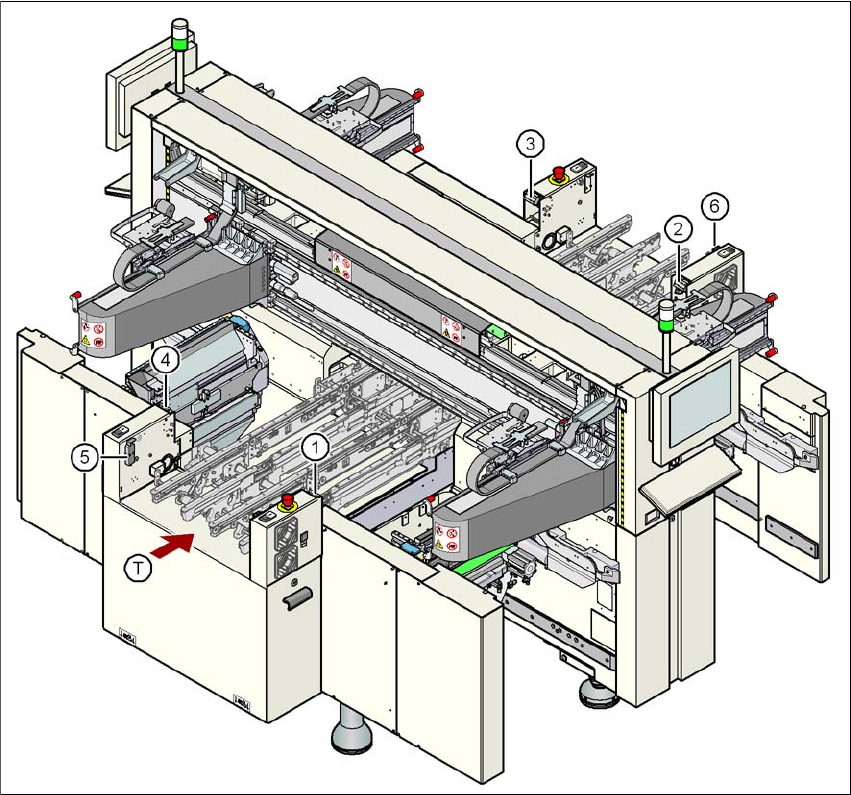
Fig. 2.6 - 5 Position of protective switches on the machine
2
(1) Protective cover switch, location 1
(2) Protective cover switch, location 2
(3) Protective cover switch, location 3
(4) Protective cover switch, location 4
(5) Protective switch for the cover flap on the PCB conveyor input side
(6) Protective switch for the cover flap on the PCB conveyor output side
(T) PCB transport direction