00196504-02_UM_X-Serie_SR70X_EN.pdf - 第81页
User manual SIPLACE X-series Operational safety From software version SR.70x.xx 01/2011 EN edition Safety equipment 81 2.6.4 Emergency stop loop s and signaling circuit 2.6.4.1 Structure of the EMERGENCY ST OP loops The …
Operational safety User manual SIPLACE X-series
Safety equipment From software version SR.70x.xx 01/2011 EN edition
80
Protective contactor combination 3TK2806 (item 1 in Fig. 2.6 - 6, page 79) 2
The protective contactor combination is contained in the power supply unit. It is used to monitor
the emergency stop circuits and safety equipment.
There are three conditions that must be fulfilled in order to activate the protective contactor com-
bination:
– The "software enable" signal must have been sent.
– The emergency stop loop must be closed.
– The start button must have been pressed.
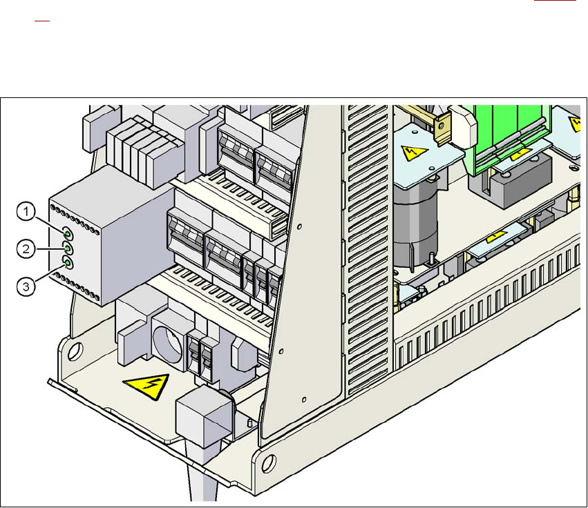
On the front panel of the protective contactor combination, there are three green operating display
LEDs (see Fig. 2.6 - 7
, page 81):
– The "Mains" LED indicates that voltage is present.
– The "Channel 1" and "Channel 2" LEDs light up if the start button was pressed, the emer-
gency stop loop is closed and the signaling circuit is not signaling a fault status.
Service socket (item 2 in Fig. 2.6 - 6, page 79) 2
The service socket is contained in the power supply unit and is protected by the cover. It can only
be used if the machine is connected to the main power supply via a 5-wire connection (L1, L2, L3,
N, and PE). If a 4-wire connection is used, e.g. without N, the socket cannot be used.
WARNING 2
Always follow the safety instructions concerning potentially lethal voltages - even when the
machine is switched off. (See Section 2.1.3 from page 38 onwards.)
User manual SIPLACE X-series Operational safety
From software version SR.70x.xx 01/2011 EN edition Safety equipment
81
2.6.4 Emergency stop loops and signaling circuit
2.6.4.1 Structure of the EMERGENCY STOP loops
The following contacts are connected in series and form the emergency stop loop:
– Normally open (NO) contacts for the four protective cover switches
– Normally open (NO) contacts in the two protective switches for the cover flaps over the PCB
conveyor
– Normally open (NO) contacts for the two emergency stop buttons
– Normally open (NO) contacts for the feeder module cover flaps (option)
– Normally open (NO) contacts for the four component trolleys
– Channels of the PCC K6 protective contactor combination
With emergency stop loop 2, the CAN bus signal from the signaling circuit (see Section 2.6.4.2
,
page 82
) is supplied to channel 2 of the protective contactor combination PCC K6. If the emer-
gency stop loop is closed, and the signaling circuit is not signaling a malfunction, then the two
green LEDs for channels 1 and 2 light up, in addition to the green mains power check LED of the
protective contactor combination.
2
Fig. 2.6 - 7 Signal LED on the protective contactor combination
(1) Netz / Power
(2) Kanal 1 / Channel 1
(3) Kanal 2 / Channel 2
Operational safety User manual SIPLACE X-series
Safety equipment From software version SR.70x.xx 01/2011 EN edition
82
2.6.4.2 Structure of the signaling circuit
The signaling contacts in the protective switches of protective covers, of cover flaps over the PCB
conveyor, of component trolleys and of emergency stop buttons are polled individually. All the sig-
naling contacts are closed when the machine is on standby. If a protective cover, for example, is
raised, the associated signaling contact opens. This change of state is signaled to the control com-
puter via the CAN bus. An error message to this effect appears on the user interface.
2.6.4.3 Description of the functions of the emergency stop loops
The following conditions must be fulfilled in order to start and operate the machine:
– All four component trolleys must be docked in and connected.
– All protective covers must be closed.
– Both cover flaps over the PCB conveyor must be closed.
– Both emergency stop buttons must be released.
– The cover flaps (option) over the feeder modules must be closed.
– The minimum operating pressure must have been reached.
– The "software enable" signal must be active. This ensures that the safety circuit is closed.
– The power supply must be sending 24 V to the start buttons and the protective contactor com-
bination.
– If one of the start buttons is now pressed, the protective contactor combination PCC K6 will
switch and activate the following components:
– 250 VDC link voltage for the servo amplifiers for the gantry axes
– 145 VDC link voltage for the star axes
– The axis unit receives a "Servo enable" signal for the servo amplifiers
– 34 VDC operating voltage is switched to the component trolleys.
– 24 VDC operating voltage is switched to the used tape cutters.
– The PCB conveyor control receives the enable signal for the PCB clamping, the PCB
stopper and the lifting table control.
The machine is then ready for use.