00196504-02_UM_X-Serie_SR70X_EN.pdf - 第84页
Operational safety User manual SIPLACE X-se ries Safety equipment From software version SR.70x.xx 01/2011 EN edition 84 2.6.5 Hand guard 2.6.5.1 Hand guard at the component trolley locations, SIPLACE X-series WA R N IN G…
User manual SIPLACE X-series Operational safety
From software version SR.70x.xx 01/2011 EN edition Safety equipment
83
2
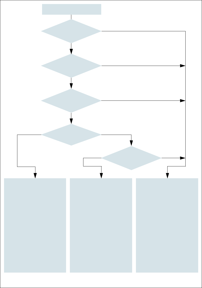
Fig. 2.6 - 8 EMERGENCY STOP loops
Start button pressed
No
No
Yes
No
No
Yes
Yes
No
Yes
2
Active
PCC
a
No
Voltage
Y axis 0 V
X axis 0 V
Star axis 0 V
DP axis 40 VDC
Z axis 40 VDC
Active
PCB conveyor Yes
Lifting table No
PCB clamping No
Width adjustment No
Laser light barrier No
Used tape cutter No
CO trolley dock. unit Yes
2
Active
PCC
a
No
Voltage
Y axis 0 V
X axis 0 V
Star axis 0 V
DP axis 40 VDC
Z axis 40 VDC
Active
PCB conveyor No
Lifting table No
PCB clamping No
Width adjustment No
Laser light barrier No
Used tape cutter No
CO trolley dock. unit Yes
a) PCC protective contactor combination K6
Yes
Compressed
air min. 0.5 MPa
(5.0 bar)?
Emergency stop button
pressed?
Protective cover open ?
Component trolley
emergency stop circuit
interrupted?
Barrier
activated on the user
interface?
2
Active
PCC
a
Yes
Voltage
Y axis 250 VDC
X axis 250 VDC
Star axis 145 VDC
DP axis 40 VDC
Z axis 40 VDC
Active
PCB conveyor Yes
Lifting table Yes
PCB clamping Yes
Width adjustment Yes
Laser light barrier Yes
Used tape cutter Yes
CO trolley dock. unit Yes
Operational safety User manual SIPLACE X-series
Safety equipment From software version SR.70x.xx 01/2011 EN edition
84
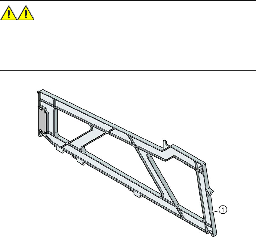
2.6.5 Hand guard
2.6.5.1 Hand guard at the component trolley locations, SIPLACE X-series
WARNING 2
Component trolleys from the SIPLACE X-series are guaranteed to be safe to use if at least every
other free location is filled with a feeder module or a hand guard (dummy feeder). When a waffle-
pack holder is set up, every other free locations should again be protected again with a hand
guard. In other words, there must be no more than one free location between two adjacent
feeder modules or feeder module and waffle-pack tray holder.
Fig. 2.6 - 9 Hand guard at the component trolley locations, SIPLACE X-series
2
(1) Dummy feeder, SIPLACE X, item no. 00141226-xx
User manual SIPLACE X-series Operational safety
From software version SR.70x.xx 01/2011 EN edition Residual voltages and discharge times in the machine
85
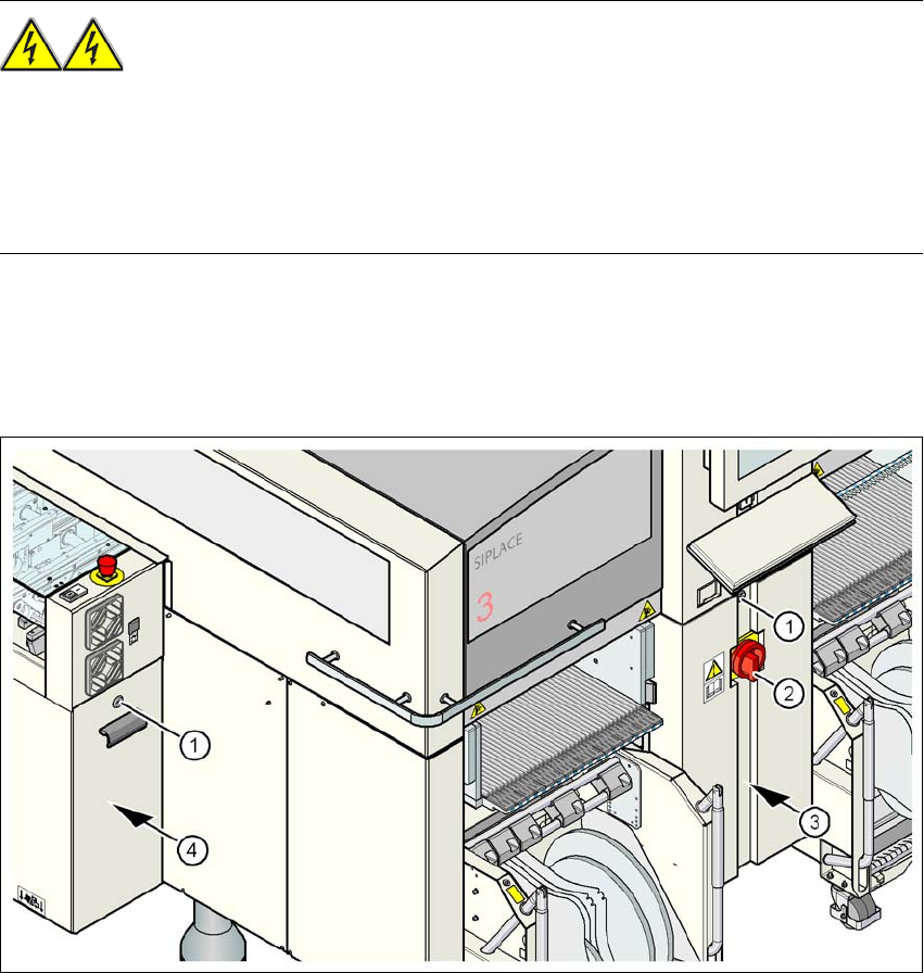
2.7 Residual voltages and discharge times in the
machine
If the emergency stop button is pressed or the machine is switched off, the 250 VDC link voltage
for the gantry axes and the 145 VDC link voltage for the star axes are reduced to harmless resid-
ual voltages in a very short time.
WARNING 2
The machine is supplied with 3 x 200 VAC, 3 x 208 VAC, 3 x 230 VAC, 3 x 380 VAC,
3 x 400 VAC or 3 x 415 VAC ± 5 %, 50/60 Hz mains voltage. This means that some parts of the
system carry potentially lethal voltages - even when switched off at the main power switch. Incor-
rect handling of the machine can therefore result in death or severe injury or considerable dam-
age to equipment.
→ Always follow the applicable accident prevention and DIN regulations (particularly DIN EN 60
204, part 1).
→ The guards over the power supply unit and the axis unit must ONLY be opened by appropri-
ately qualified and trained personnel.
2
Fig. 2.7 - 1 Power supply unit
(1) Padlock with bolt in the cover
(2) Main power switch
(3) Power supply unit behind the cover
(4) Axis unit