00196504-02_UM_X-Serie_SR70X_EN.pdf - 第87页
User manual SIPLACE X-series Operational safety From software version SR.70x.xx 01/2011 EN edition Disabling the compressed air supply and discharging the pressure 87 2.7.2 Residual volt ag es and discharge times af ter …
Operational safety User manual SIPLACE X-series
Residual voltages and discharge times in the machine From software version SR.70x.xx 01/2011 EN edition
86
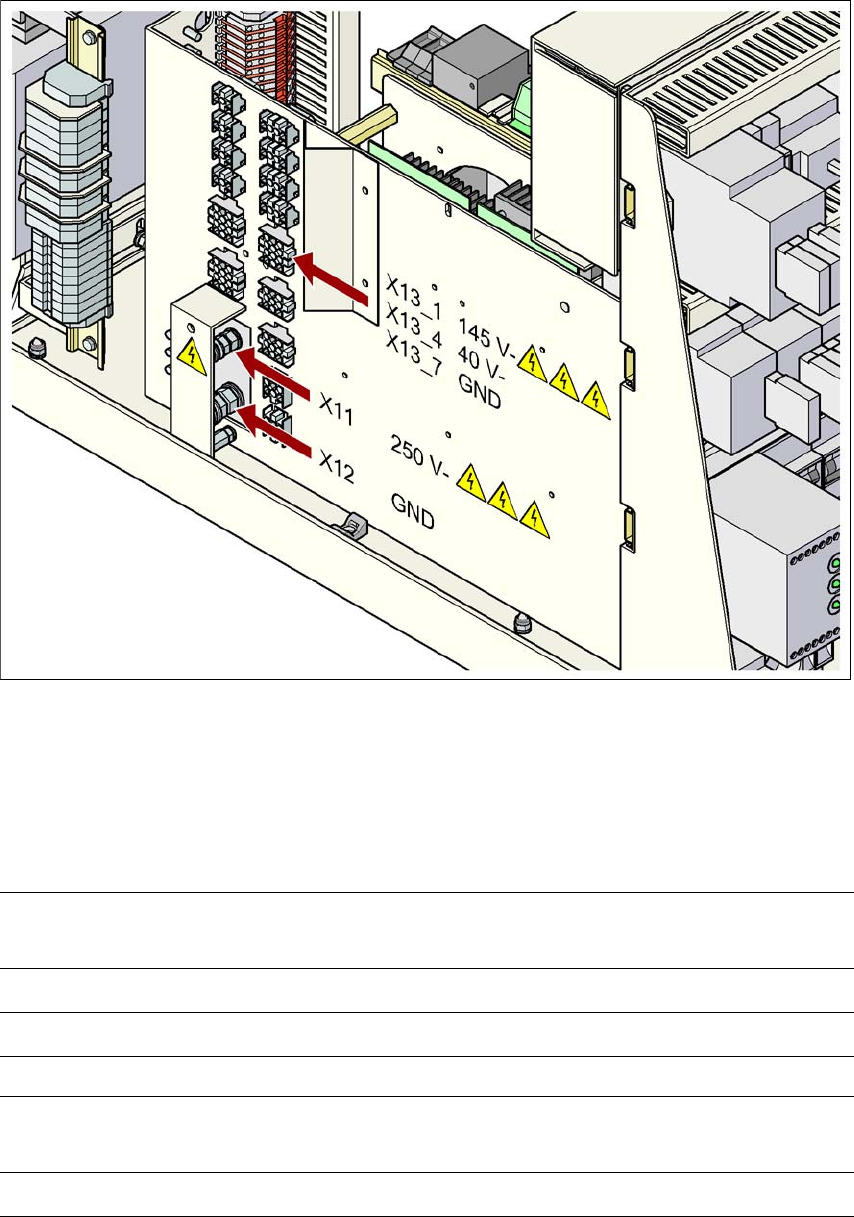
Fig. 2.7 - 2 Measuring points on the power supply unit
2
2.7.1 Operating voltages, residual voltages and discharge times after pressing
the emergency stop button
2
2
Pins X11 and X13_1
measured to X12 (GND)
Voltage in
normal mode
Residual voltage after
emergency stop
Discharge
times
X11 + 250 VDC < 10 VDC 7 s
X13_1 + 145 VDC < 10 VDC 50 s
Pin X13_4
measured to pin X3_7 (-)
Voltage in
normal mode
Residual voltage after
emergency stop
Discharge
times
X13_4 + 40 VDC + 40 VDC -
User manual SIPLACE X-series Operational safety
From software version SR.70x.xx 01/2011 EN edition Disabling the compressed air supply and discharging the pressure
87
2.7.2 Residual voltages and discharge times after switching off at the main switch
2
CAUTION 2
To avoid losing data, assess the following criteria before switching off your machine (apart from
in emergencies):
– Has the machine finished transmitting machine, setup and panel data?
– Has the machine finished processing the PCB?
– Has the machine completed the run-up phase?
2.8 Disabling the compressed air supply and discharg-
ing the pressure
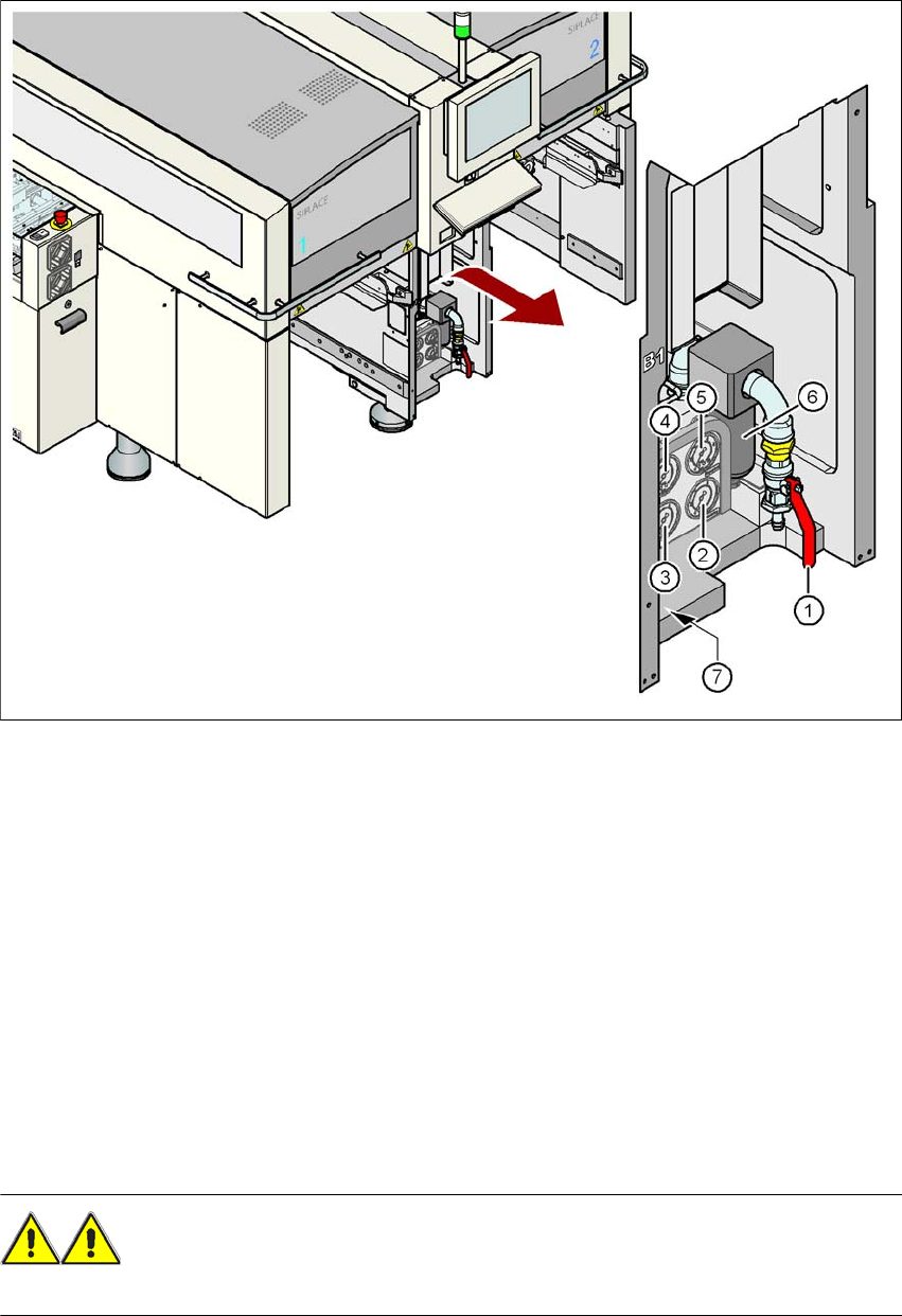
The compressed air working pressure of the machine is set to 0.50 ± 0.025 MPa (5.0 ± 0.25 bar).
The position of the compressed air unit is indicated by item 1 in Fig. 2.8 - 1
, page 88. The com-
pressed air supply to the machine can be interrupted using the shutoff valve (item 2 in Fig.
2.8 - 1
, page 88).
→ Use the machine key to release the cover lock.
→ Lift off the cover (see Fig. 2.8 - 1
, page 88).
→ Turn the lever on the shutoff valve (item 1 in Fig. 2.8 - 1
, page 88) from the vertical to the
horizontal position.
→ Watch the working pressure gauge (item 5 in Fig. 2.8 - 1
, page 88). When the machine is
switched on, the pressure discharges to 0 MPa (0 bar) within 1 minute.
CAUTION
When the machine is switched on, do not use the stop valve to interrupt the compressed air sup-
ply for more than 30 minutes. If you need to shut off the pneumatic system for longer in order to
carry out preventive maintenance or servicing work, you must switch the machine off at the main
switch and disconnect it from the power supply.
Pins X11, X13_1 and X13_4
measured to X12 (GND)
Residual voltages when
main power switch is off Discharge times
X11 < 10 VDC < 7 s
X13_1 < 10 VDC < 50 s
X13_4 < 10 VDC < 2 s
Operational safety User manual SIPLACE X-series
Disabling the compressed air supply and discharging the pressure From software version SR.70x.xx 01/2011 EN edition
88
Fig. 2.8 - 1 Compressed air unit on the machine
(1) Stop valve
(2) Manometer for the machine component supply pressure
Desired pressure: 0.48 ± 0.025 MPa, 4.8 ± 0.25 bar (display range: 0 - 0.6 MPa, 0 - 6 bar)
(3) Manometer for the gantry distributor supply pressure
Desired pressure: 0.46 ± 0.01 MPa, 4.6 ± 0.1 bar (display range: 0 - 0.6 MPa, 0 - 6 bar)
(4) Manometer for the bulk case feeder modules supply pressure
Desired pressure: 0.25 ± 0.05 MPa, 2.5 ± 0.5 bar (display range 0 - 0.6 MPa, 0 - 6 bar)
(5) Manometer for the input pressure
Desired pressure: 0.5 - 1.0 MPa, 5 - 10 bar (display range: 0 - 1.0 MPa, 0 - 10 bar)
(6) Compressed air filter
(7) Hexagon socket head screw for fixing the pneumatic unit
WARNING
NEVER detach compressed air lines while they are still pressurized. Risk of injury. 2