00196504-02_UM_X-Serie_SR70X_EN.pdf - 第92页
Operational safety User manual SIPLACE X-se ries Energy state of the machine after switching off at the main power switch From software version SR.70x.xx 01/2011 EN edition 92 2 Fig. 2.9 - 3 Power supply unit, back view …
User manual SIPLACE X-series Operational safety
From software version SR.70x.xx 01/2011 EN edition Energy state of the machine after switching off at the main power switch
91
2
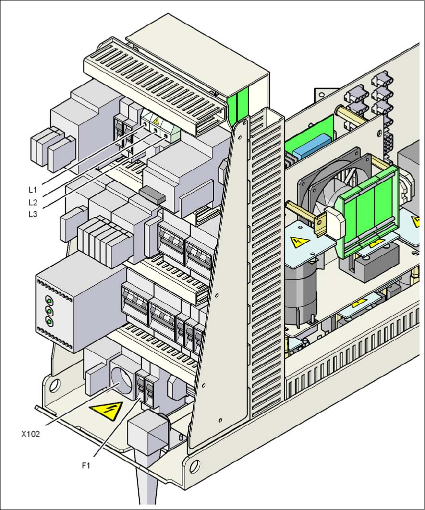
Fig. 2.9 - 2 Power supply unit, front view
Q1 Main power switch
X102 Service socket
F1 Fuse for the service socket
Operational safety User manual SIPLACE X-series
Energy state of the machine after switching off at the main power switch From software version SR.70x.xx 01/2011 EN edition
92
2
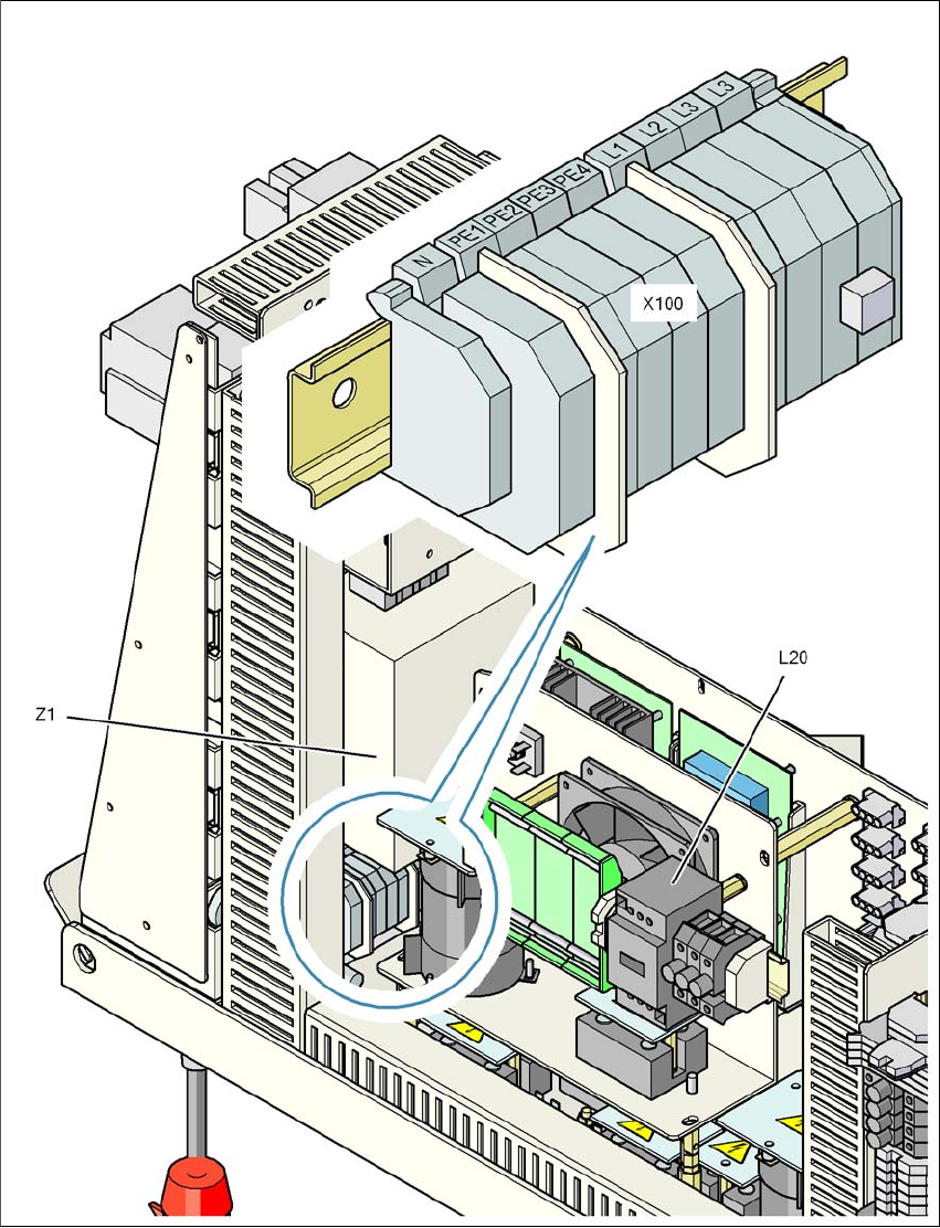
Fig. 2.9 - 3 Power supply unit, back view
X100 Cable connection terminal for the power supply cable
L20 Discharge reactor with fuses F21, F22 and F23
Z1 Line filter
User manual SIPLACE X-series Operational safety
From software version SR.70x.xx 01/2011 EN edition Energy state of the machine after switching off at the main power switch
93
The following table specifies the voltages of modules when the machine is switched off at the main
switch, but still connected to the mains supply.
2
2.9.2 Machine switched off at the main power switch and disconnected
The machine is unpowered, apart from slight residual voltages in the power supply unit.
Module Voltage
Terminal panel X100
Line filter Z1
Terminals L1, L2, L3
3 x 200 VAC
3 x 208 VAC
3 x 230 VAC
3 x 380 VAC
3 x 400 VAC
3 x 415 VAC
Service socket X102
115 VAC
120 VAC
130 VAC
220 VAC
230 VAC
240 VAC
Automatic circuit breaker F1
115 VAC
120 VAC
130 VAC
220 VAC
230 VAC
240 VAC
Main switch Q1
Terminals L1, L2, L3
3 x 200 VAC
3 x 208 VAC
3 x 230 VAC
3 x 380 VAC
3 x 400 VAC
3 x 415 VAC
Main switch Q1
Terminals T1, T2, T3 0 VAC
Power supply unit
(see item 5 in Fig. 2.7 - 2
, page 86)
Test socket X11
GND X12
Test socket X13_1
Test socket X13_4
GND X13_7
< 10 VDC
< 10 VDC
< 10 VDC