00197467-01_SM_DLM3-4_Kunde_en.pdf - 第20页
Service Work Removal/Installation of Head Front Part 20 Service Manual SIPLACE Placement Heads DLM3/DLM4 Preparation ► Remove the head from the machine. For details about removing an d fitting the placement head, refer t…
Service Work
Exchange the Placement head
Service Manual SIPLACE Placement Heads DLM3/DLM4 19
3
3 Service Work
Service Work
3.1
3.1 Exchange the Placement head
Exchange the Placement head
► For removal and installation details of the placement head, read the service manual for your ma
-
chine.
3.2
3.2 Removal/Installation of Head Front Part
Removal/Installation of Head Front Part
Parts, equipment and tools
▪ Set of Allen keys.
▪ Torx Allen screwdriver TX8 [03080081-xx]
▪ Calibration tool version 3 [03010565-xx]
▪ Assembling instruction for "component sensor" [00193356-xx], if necessary
Overview
NOTICE
Differences between the various DLM heads
The instructions apply in principle to all DLM head variants.
Any differences will be explicitly indicated.
NOTICE
Additional work
► If you need to perform further work on this head (e.g. replacing spare parts), fit the head to
the head mount [03056231-xx].
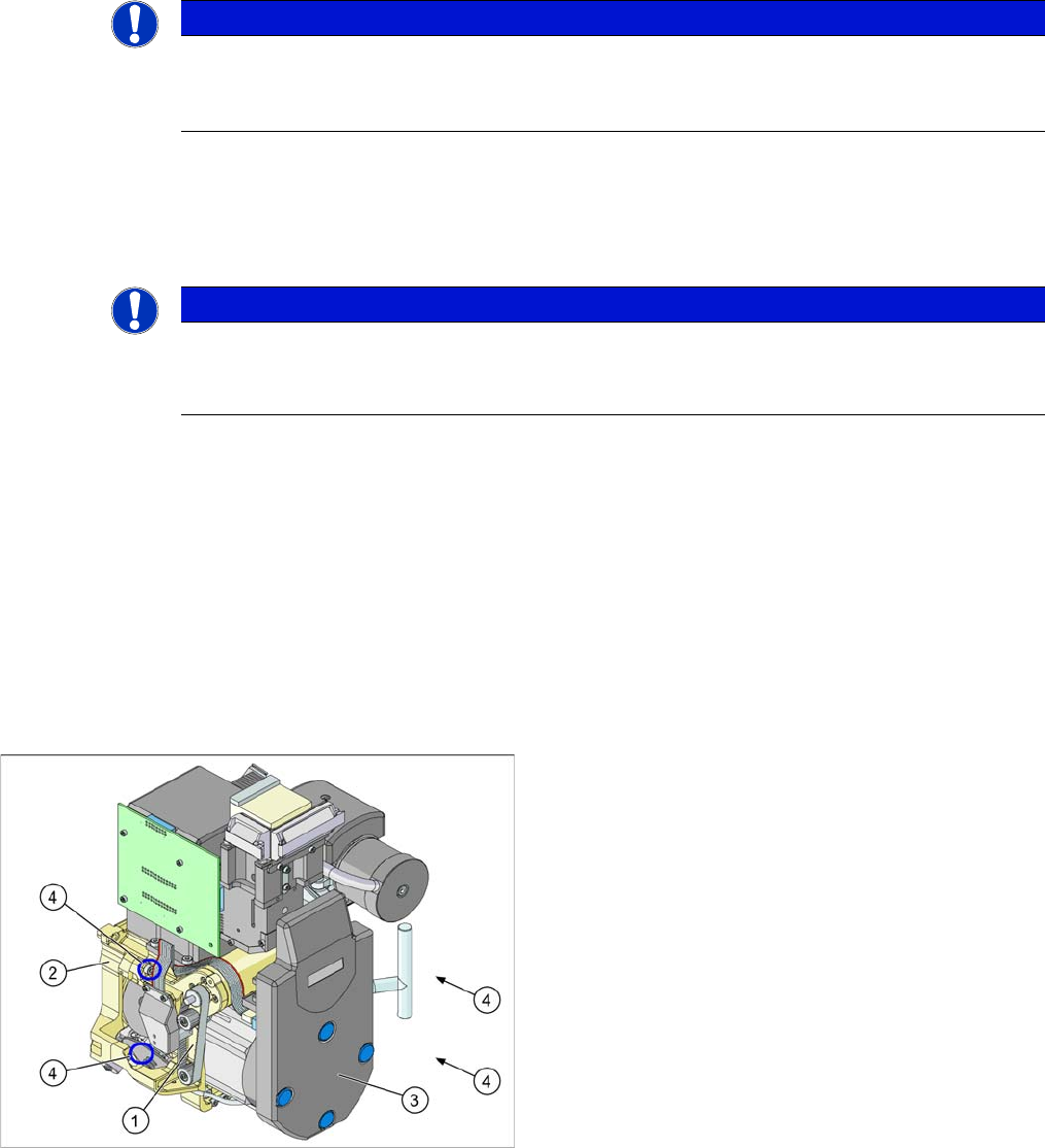
1. Front part
2. Back part
3. Intermediate distributor (under the cover)
4. Fastening screws (4x) for the front part of the head
Service Work
Removal/Installation of Head Front Part
20 Service Manual SIPLACE Placement Heads DLM3/DLM4
Preparation
► Remove the head from the machine. For details about removing and fitting the placement head, refer
to the service manual for your machine.
Removal
► Switch off the machine and secure it to prevent unauthorized reactivation.
► Remove the head from the machine.
► If you have not dismantled the head from the gantry: pull the connection cable plug off the gantry
board.
► Remove the compressed air hose for the blast air.
► DLM3 only: If required, loosen the screws fastening the C&P12 component sensor option. Observe
the assembly instructions "component sensor" [DE+EN: 00193356
-
xx].
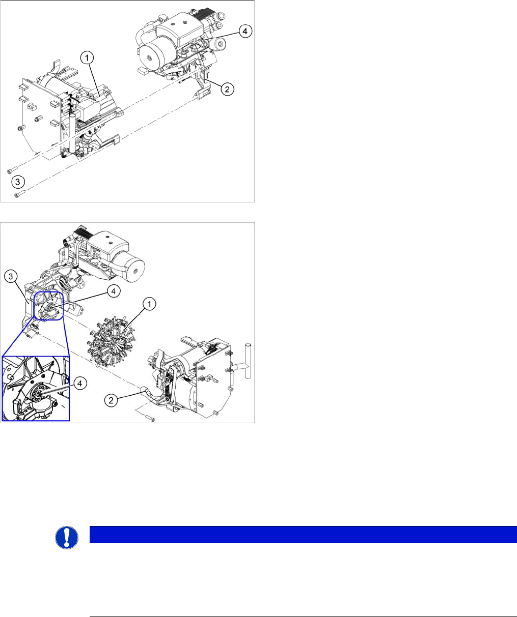
1. Front part
2. Back part
3. Fastening screws (4x) for the front part of the head
4. Compressed air hose for blast air
1. Star
2. Front part
3. Back part
4. Vacuum distributor block
NOTICE
Avoid confusing the front and back sections of different heads
The front and back parts of each specific head belong together.
► Make sure that the front and back part of the head always have the same serial number.
Do not confuse these parts with parts from other heads, which have different serial num
-
bers.
Service Work
Removal/Installation of Head Front Part
Service Manual SIPLACE Placement Heads DLM3/DLM4 21
► Loosen the four screws fastening the front part of the head.
► Pull the front part of the head off the parallel pins on the back part and place it on a clean, soft and
ESD-proof surface.
► You will find the vacuum distributor block loose (unconnected) on the back part of the machine. Re
-
move this vacuum distributor block.
Installation
CAUTION
Keep hold of the head and make sure the star position is correct!
► When you undo the last screw, hold the head firmly so that it does not accidentally drop off
the back part.
► When you remove the front part of the head, make sure that the star is rotated roughly 30°
or 15° out of the vertical sleeve position. If not, the valve plunger will remain attached to the
valve adjustment drive.
NOTICE
Vacuum distributor block
The vacuum distributor block is normally clamped between the front and back parts of the ma
-
chine and transmits the vacuum for the holding circuit.
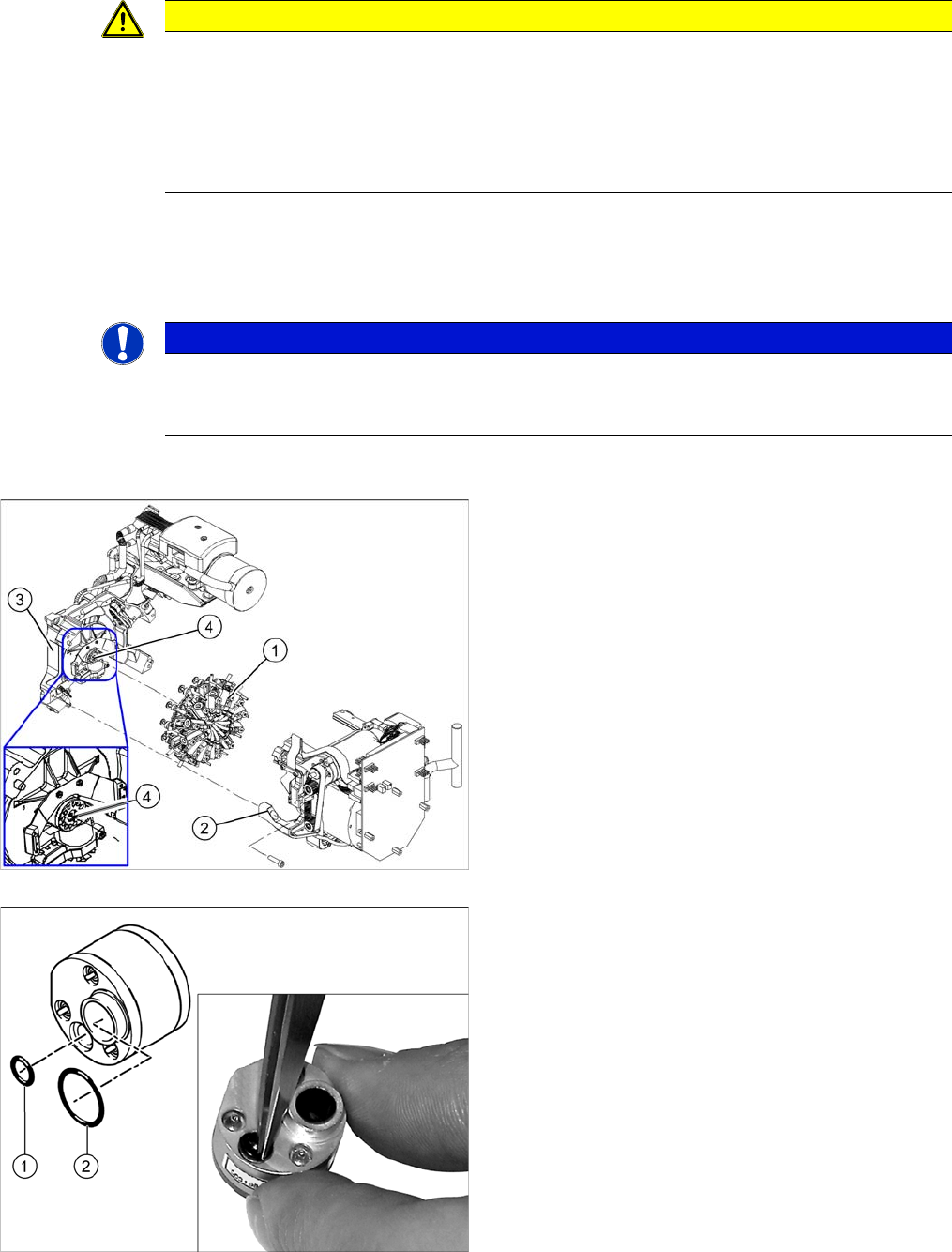
1. Star
2. Front part
3. Back part
4. Vacuum distributor block
► Grease the O-rings of the vacuum distributor with
Unisilikon.
► Push the small O
-
ring (1) onto the tube.
► Place the large O-ring (2) on the vacuum distributor
block.
► Check that the O-rings are fitted correctly.