00197467-01_SM_DLM3-4_Kunde_en.pdf - 第30页
Service Work Replacing the Valve Positioning D rive for the Placement Circuit [00368075- xx] 30 Service Manual SIPLACE Placement Heads DLM3/DLM4 3.8 3 . 8 R e p la c in g t h e V a lv e P o s it io n in g D r iv e f o r …
Service Work
Replacing the Toothed Belt for the DLM Turning Station (from version 07)
Service Manual SIPLACE Placement Heads DLM3/DLM4 29
3.7
3.7 Replacing the Toothed Belt for the DLM Turning Station (from version 07) [00320041-xx]
Replacing the Toothed Belt for the DLM Turning Station (from
version 07) [00320041-xx]
Parts, equipment and tools
Preparation
► Remove the head from the machine. For details about removing and fitting the placement head, refer
to the service manual for your machine.
Removal/installation
► Further installation is performed by following the above instructions in the reverse order. Also ob
-
serve the following instructions:
Belt tensioning device for turning station DLM
▪ Belt tensioning device for turning station DLM
[03063649
-
xx]
▪ Lubricant Isoflex Topas NCA52
▪ Synchroflex toothed belt 2.5 T2/90 [00320041
-
xx]
► Remove the turning station (see "3.5 Replacing the
Turning Station" [ ➙ 25]).
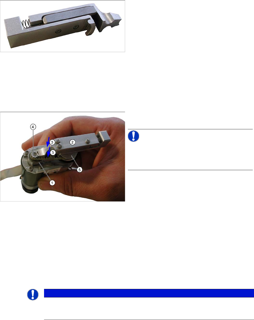
NOTICE!
To loosen or tighten the fastening screw on the rocker,
hold the DP station between your thumb and index finger
so that the swivel-in rocker (1) can be moved to the left
and right.
► Remove the defective toothed belt.
► Loosen the two fastening screws (3) with a size 0
screwdriver. Do not fully remove the screws (leave
them in the unit).
► Grease the new toothed belt slightly with Isoflex
Topas NCA52.
► Fit the new toothed belt onto the toothed wheels.
► Fit the adjustment aid (2) between the motor drive
toothed wheel (4) and the sleeve drive wheel (5). The
tension of the steel spring in the tool sets the belt to
the correct tension.
► Now tighten the two screws fastening (3) the rocker
with a size 0 screwdriver.
NOTICE
Installation instructions
► Check the axis dynamics. Read the service manual or settings manual for your machine
first.
Service Work
Replacing the Valve Positioning Drive for the Placement Circuit [00368075-xx]
30 Service Manual SIPLACE Placement Heads DLM3/DLM4
3.8
3.8 Replacing the Valve Positioning Drive for the Placement Circuit [00368075-xx]
Replacing the Valve Positioning Drive for the Placement Circuit
[00368075-xx]
Parts, equipment and tools
▪ Distance gauge 0.2 mm [00325445-01] – used up to version 2.
▪ Adjustment valve plunger for placement circuit [03068816-xx]
These are needed for the DLM2, DLM3 and DLM4.
Overview
Preparation
► Remove the head from the machine. For details about removing and fitting the placement head, refer
to the service manual for your machine.
Removal
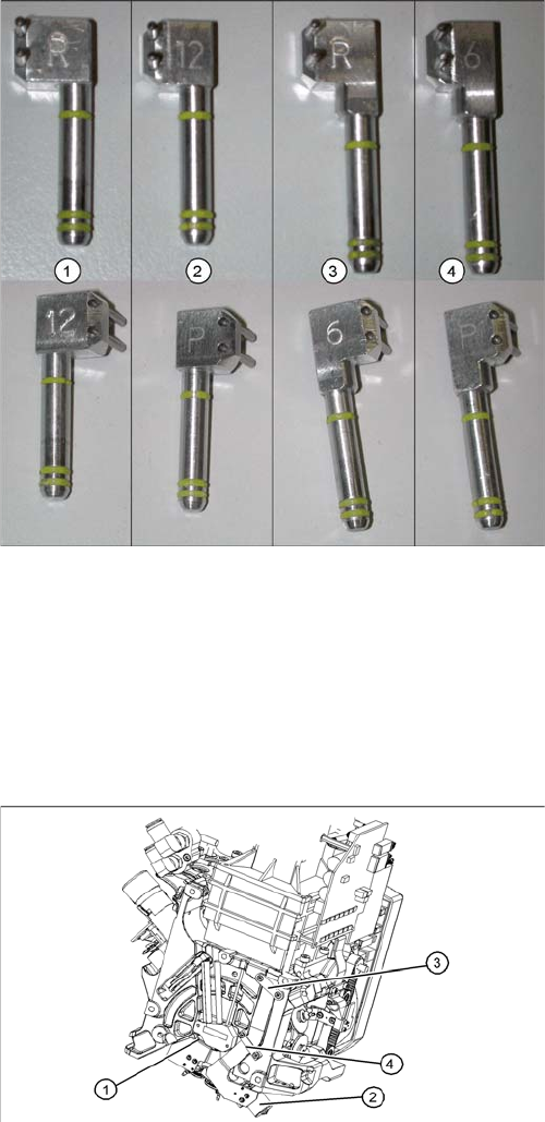
Adjustment valve plunger DLM head
Adjustment valve plunger
Available from positioning unit version 3
Use the 0.2 mm setting gauge with DLM1.
1. Adjustment valve plunger for reject circuit C&P12
[03064290-xx] (DLM2, DLM3)
2. Adjustment valve plunger for placement circuit
C&P12 [03068816-xx] (DLM2, DLM3, DLM4)
3. Adjustment valve plunger for reject circuit C&P6
[03068854
-
xx] (DLM2, DLM3)
The C&P6 is not used in the DX series.
4. Adjustment valve plunger for placement circuit C&P6
[03065628
-
xx] (DLM2, DLM3)
The C&P6 is not used in the DX series.
The labeling on the plungers has the following meaning:
▪ 6 = DLM head with 6 segments
▪ 12 = DLM head with 12 segments
▪ P = placement circuit
▪ R = reject circuit
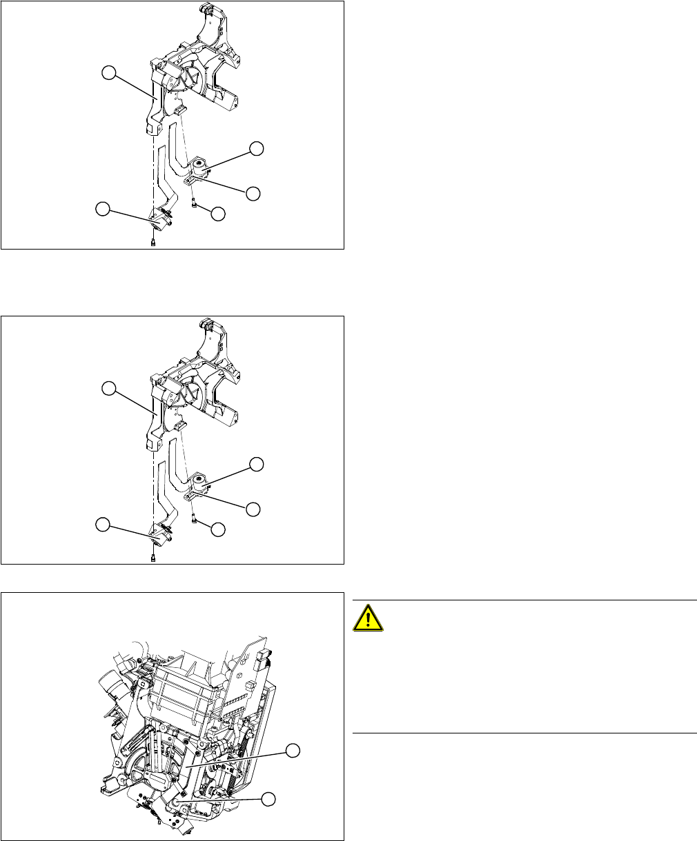
1. Valve positioning drive for placement circuit
[00368075-xx]
(DLM2, DLM3, DLM4)
2. Valve positioning drive for reject circuit [00367768-
xx]
(DLM2, DLM3, not DLM4)
3. Flat ribbon cable clamp
4. Flat ribbon cable clamp
► Loosen the two Phillips screws on the flat ribbon ca
-
ble clamp (3) and (4).
Service Work
Replacing the Valve Positioning Drive for the Placement Circuit [00368075-xx]
Service Manual SIPLACE Placement Heads DLM3/DLM4 31
Installation
► Further installation is performed by following the above instructions in the reverse order.
1. Valve positioning drive for placement circuit
[00368075-xx]
(DLM2, DLM3, DLM4)
2. Valve positioning drive for reject circuit [00367768-
xx]
(DLM2, DLM3, not DLM4)
► Loosen the fastening screw (4).
► Carefully remove the valve positioning drive (1).
5
1
4
3
2
► Insert the valve positioning drive. Make sure that it is
seated correctly on the parallel pins (5).
► Loosely screw in the hexagon socket-head screw (4).
► Use the cable clamps to fix the ribbon cable in posi
-
tion. Make sure that the ribbon cables are not
pinched.
CAUTION!
Check how the cables are run!
Check that the ribbon cables are laid correctly (1).
The flat ribbon cable for the two valve positioning units
must be run outside the holes (2). It will otherwise be
damaged when the head is fitted onto the head plate.
5
1
4
3
2
1
2