00197467-01_SM_DLM3-4_Kunde_en.pdf - 第32页
Service Work Replacing the Valve Positioning D rive for the Placement Circuit [00368075- xx] 3.8.1 New Valve Positioning Drives (From Version 03) 32 Service Manual SIPLACE Placement Heads DLM3/DLM4 3.8.1 3 . 8 . 1 N e w …
Service Work
Replacing the Valve Positioning Drive for the Placement Circuit [00368075-xx]
Service Manual SIPLACE Placement Heads DLM3/DLM4 31
Installation
► Further installation is performed by following the above instructions in the reverse order.
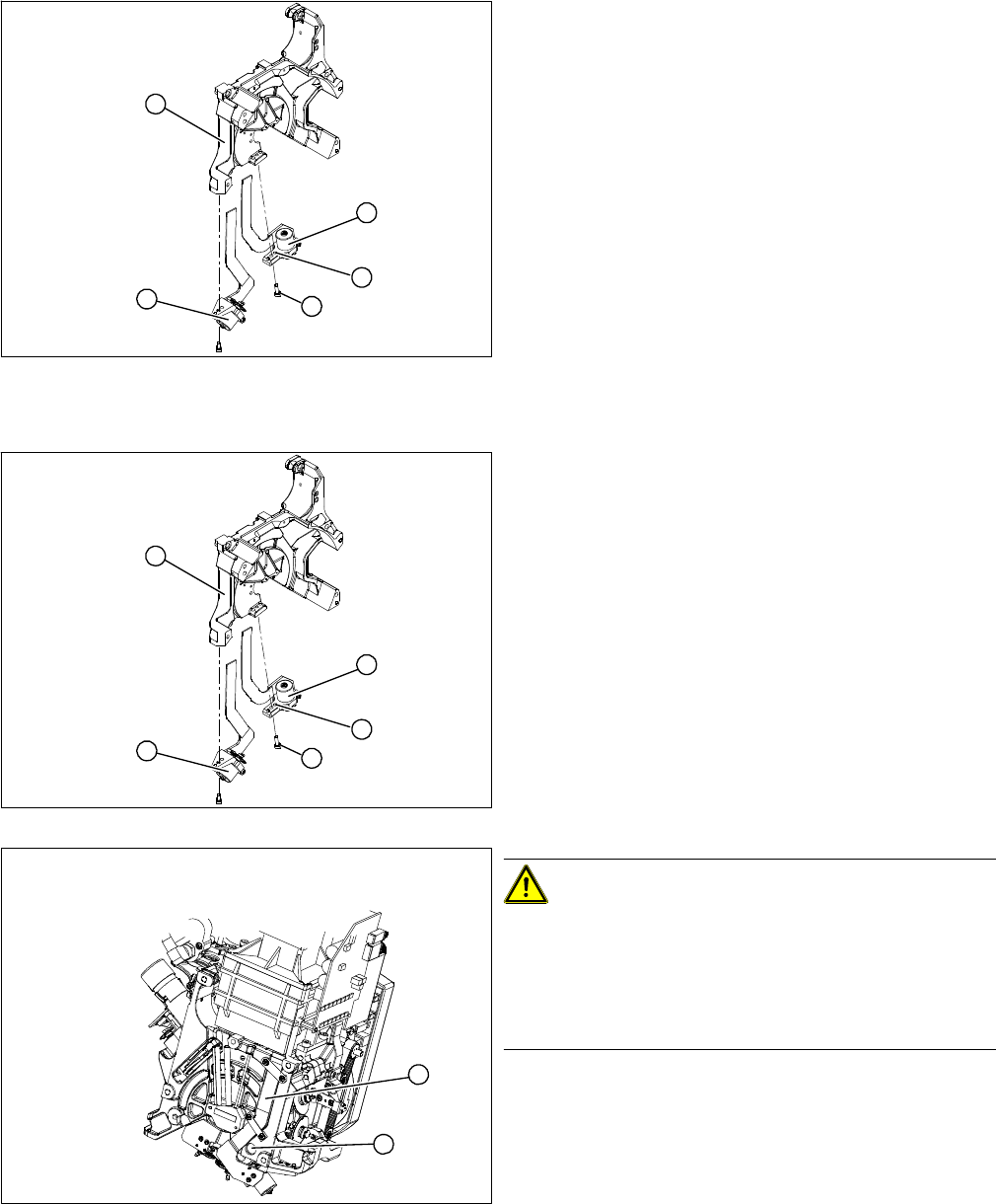
1. Valve positioning drive for placement circuit
[00368075-xx]
(DLM2, DLM3, DLM4)
2. Valve positioning drive for reject circuit [00367768-
xx]
(DLM2, DLM3, not DLM4)
► Loosen the fastening screw (4).
► Carefully remove the valve positioning drive (1).
5
1
4
3
2
► Insert the valve positioning drive. Make sure that it is
seated correctly on the parallel pins (5).
► Loosely screw in the hexagon socket-head screw (4).
► Use the cable clamps to fix the ribbon cable in posi
-
tion. Make sure that the ribbon cables are not
pinched.
CAUTION!
Check how the cables are run!
Check that the ribbon cables are laid correctly (1).
The flat ribbon cable for the two valve positioning units
must be run outside the holes (2). It will otherwise be
damaged when the head is fitted onto the head plate.
5
1
4
3
2
1
2
Service Work
Replacing the Valve Positioning Drive for the Placement Circuit [00368075-xx] 3.8.1 New Valve Positioning Drives (From Version 03)
32 Service Manual SIPLACE Placement Heads DLM3/DLM4
3.8.1
3.8.1 New Valve Positioning Drives (From Version 03)
New Valve Positioning Drives (From Version 03)
New valve positioning drives are now available which guarantee a reliable assembly position even if the
head is incorrectly placed down on its back.
The valve positioning drive can ONLY be fitted when the head has been dismantled, as the locking
threaded pin (Allen key, M1, 4x4) is only accessible from the back of the head.
New valve positioning drive holder for star placement po
-
sition with position locking
The holder for the valve positioning drives of the place
-
ment and reject positions has an additional threaded pin.
After the motor mount has been fastened, this threaded
pin is tightened until it just touches the centering pin. The
valve positioning drive is now fixed so that its position can
not change towards the front.
Additional improvements have also been made to individ
-
ual parts of the valve positioning drive.
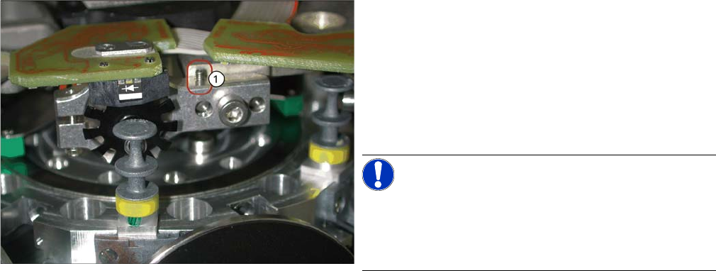
NOTICE!
This holder also fits the valve positioning drive on the
placement and reject position of the DLM1 head. A sec
-
ond 1.4 mm thread (1) is provided on the opposite side
for this purpose.
Service Work
3.8.2 Mechanical Adjustment (Up To Version 02) Replacing the Valve Positioning Drive for the Placement Circuit [00368075-xx]
Service Manual SIPLACE Placement Heads DLM3/DLM4 33
3.8.2
3.8.2 Mechanical Adjustment (Up To Version 02)
Mechanical Adjustment (Up To Version 02)
NOTICE
Distance gauge
Instead of using the adjustment valve plungers, the DLM1 and DLM2 heads can also be set
with the distance gauge.
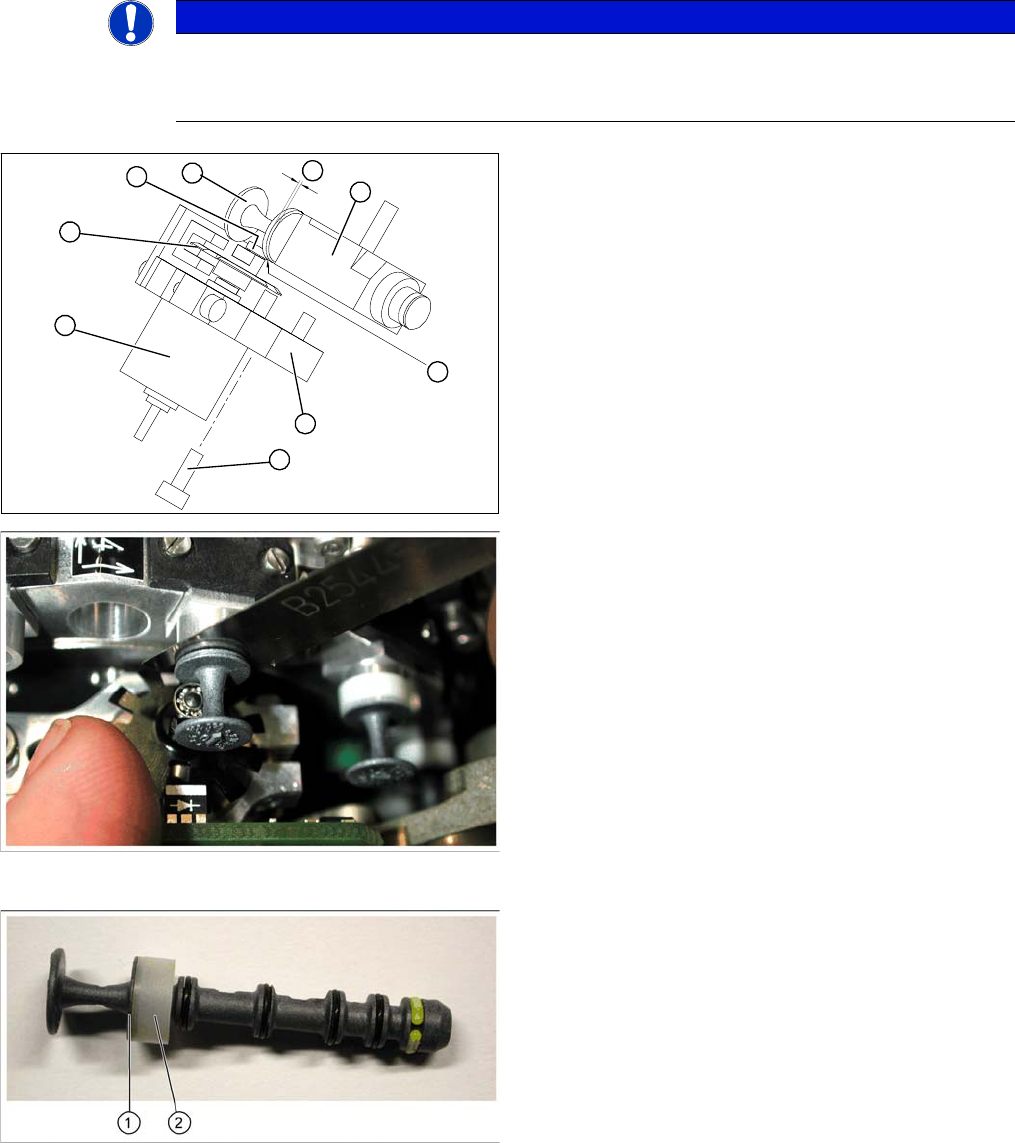
1. Stepping motor
2. Cam disk
3. Deep-groove ball bearings
4. Valve plunger
5. Valve casing
6. M3x10 hexagon socket-head screw
7. Valve positioning drive (flange)
► Use the feeler gauge to set the distance between the
valve plunger and valve casing to 0.2 mm (A).
► Turn the cam disk (2) until the deep-groove ball bear
-
ings (3) point towards the valve casing.
► Move the valve positioning drive (7) so that the deep-
groove ball bearings (3) come into contact with the
valve plunger (4) at position (B).
► Use the hexagon socket-head screw to fix the adjust
-
ment unit in this position (6).
► Fit the head.
► Check that the valve positioning drive is functioning
correctly.
► Calibrate the head.
Valve plunger version 03
(C&P12: [00351498
-
03], C&P6: [00351500
-
03])
► If new valve plungers (see diagram on left) are used,
proceed as follows:
⇨ Take out one valve plunger and remove the sleeve
(2).
⇨ Insert the plunger without bushing and carry out
the following steps on this segment.
► Insert the distance gauge (0.2 mm) between valve
plunger and valve casing.
► Rotate the valve positioning drive 90 degrees from its
initial position. The eccentric of the valve adjustment
drive will just touch the inner side (1) of the valve
plunger.
► Fix the motor of the valve positioning drive in this po
-
sition.
► Remember to replace the tube on the valve plunger.
B
A
1
7
6
5
4
3
2