00197467-01_SM_DLM3-4_Kunde_en.pdf - 第43页
Service Work 3.9.3 Mechanical Adjustment (From Version 03) Replacing the Z Ax is Driv e Service Manual SIPLACE Placement Heads DLM3/DLM4 43 3.11 3 . 1 1 R e p la c in g t h e Z A x is D r iv e Replacing the Z Axis Drive …
Service Work
Replacing the Light Barrier "Z Axis Up" [03053294-xx] 3.9.3 Mechanical Adjustment (From Version 03)
42 Service Manual SIPLACE Placement Heads DLM3/DLM4
3.10
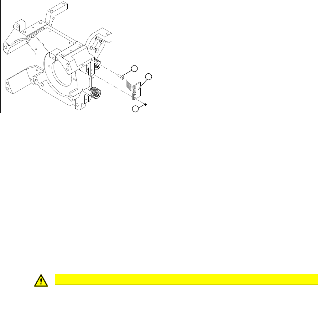
3.10 Replacing the Light Barrier "Z Axis Up" [03053294-xx]
Replacing the Light Barrier "Z Axis Up" [03053294-xx]
Parts, equipment and tools
▪ Light barrier, Z axis up DLM1/2/3 [03053294-xx]
Overview
Preparation
► Remove the head from the machine. For details about removing and fitting the placement head, refer
to the service manual for your machine.
Removal
► Switch off the machine and secure it to prevent unauthorized reactivation.
► Remove the plug from the slot on the intermediate distributor.
► Undo the two hexagon socket-head screw (1) and remove the flat ribbon cable clamp.
► Loosen the two slotted screws (2).
► Remove the light barrier "Z axis up" (3) with its cable.
► Use the two slotted screws (2) to fix the "Z axis up" light barrier board (3). Move the board as far
upwards as the screws will tolerate.
► Connect the ribbon cable plug to the slot on the intermediate distributor.
► Use the flat ribbon cable clamp and the two hexagon socket-head screws (1) to fix the flat ribbon
cables.
► Further installation is performed by following the above instructions in the reverse order.
1. 2 x M2.0x4 hexagon socket-head screws
2. 2 x slotted screws
3. Light barrier board "Z axis up"
1
3
2
CAUTION
Check how the cables are run!
► Make sure that the flat ribbon cable is not pinched in the guide channel. Make sure that you
push the folded part of the flat ribbon cable for the "Z axis up" light barrier back under the
illumination board.
► Note: a new version is available with a shortened flat ribbon cable.
Service Work
3.9.3 Mechanical Adjustment (From Version 03) Replacing the Z Axis Drive
Service Manual SIPLACE Placement Heads DLM3/DLM4 43
3.11
3.11 Replacing the Z Axis Drive
Replacing the Z Axis Drive
Parts, equipment and tools
▪ DLM1, DLM2, DLM3: Z motor with interference suppression board [03038908-xx]
▪ DLM4: Z motor with interference suppression board [03083864-xx]
Preparation
► Remove the head from the machine. For details about removing and fitting the placement head, refer
to the service manual for your machine.
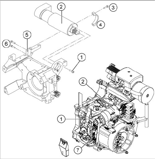
Overview
Removal
► Switch off the machine and secure it to prevent unauthorized reactivation.
► Remove the head from the machine.
► Remove the plugs (motor tacho and incremental encoder) from the sockets on the intermediate dis
-
tributor.
► Loosen the four M3x5 hexagon socket-head screws which have been fixed with locking varnish (1).
► First loosen the upper M2.5x12 hexagon socket-head screw (3) of the motor clamp fitting 2 (4), then
the lower one.
► Loosen the two M3x14 hexagon socket-head screws (6) on the motor clamp fitting (5).
► Carefully remove the Z axis drive (2) together with the cables.
1. Hexagon socket-head screws M3x5 with locking var
-
nish (4x)
2. Z axis drive
3. Hexagon socket-head screws M2.5x12 (2x)
4. Motor clamp upper part /DLM3
5. Motor clamp/DLM3 (do not confuse this with the as
-
sembly clamp for the Z motor tacho interference sup
-
pression board)
6. Hexagon socket-head screws M3x14 (2x)
7. Toothed belt
Service Work
Replacing the Z Axis Drive 3.9.3 Mechanical Adjustment (From Version 03)
44 Service Manual SIPLACE Placement Heads DLM3/DLM4
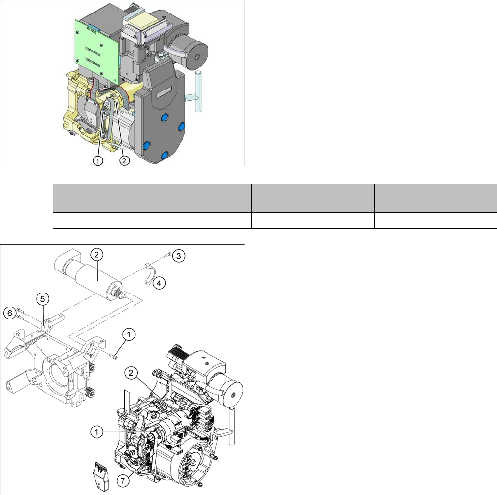
Installation
► Further installation is performed by following the above instructions in the reverse order.
► Insert the Z axis drive (2).
► Make sure that the teeth of the toothed belt (7) en
-
gage in the teeth of the motor pinion (1).
► Use the four M3x5 hexagon socket-head screws to fit
the Z axis drive.
► Tension the Z axis toothed belt by moving the Z axis
drive unit upwards and fix the motor with at least one
screw.
► Check the toothed belt tension with the belt tension
measuring device.
Frequency in Hz Before continuous opera
-
tion run
After continuous operation
run
Toothed belt T2 / DLM3 on the Z axis 280 +/- 10 280 +/- 10
► Tighten the two M3x14 hexagon socket-head screws
(6) to fix the motor clamp (5).
► Fix the motor clamp upper part (4) with the two
M2.5x12 hexagon socket-head screws (3).
► Now tighten the hexagon socket-head screws on the
Z axis drive unit and the motor clamp.
► Check the Z axis top stop with the setting gauge.