00197467-01_SM_DLM3-4_Kunde_en.pdf - 第44页
Service Work Replacing the Z Axis Drive 3.9.3 Mechanical Ad justment (From Ver sion 03) 44 Service Manual SIPLACE Placement Heads DLM3/DLM4 Installation ► Further installation is performe d by following the above instru …
Service Work
3.9.3 Mechanical Adjustment (From Version 03) Replacing the Z Axis Drive
Service Manual SIPLACE Placement Heads DLM3/DLM4 43
3.11
3.11 Replacing the Z Axis Drive
Replacing the Z Axis Drive
Parts, equipment and tools
▪ DLM1, DLM2, DLM3: Z motor with interference suppression board [03038908-xx]
▪ DLM4: Z motor with interference suppression board [03083864-xx]
Preparation
► Remove the head from the machine. For details about removing and fitting the placement head, refer
to the service manual for your machine.
Overview
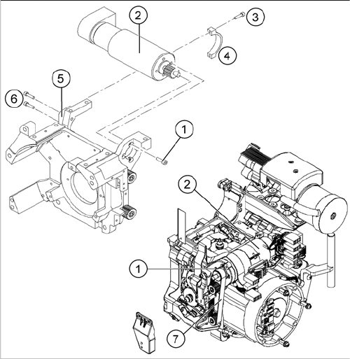
Removal
► Switch off the machine and secure it to prevent unauthorized reactivation.
► Remove the head from the machine.
► Remove the plugs (motor tacho and incremental encoder) from the sockets on the intermediate dis
-
tributor.
► Loosen the four M3x5 hexagon socket-head screws which have been fixed with locking varnish (1).
► First loosen the upper M2.5x12 hexagon socket-head screw (3) of the motor clamp fitting 2 (4), then
the lower one.
► Loosen the two M3x14 hexagon socket-head screws (6) on the motor clamp fitting (5).
► Carefully remove the Z axis drive (2) together with the cables.
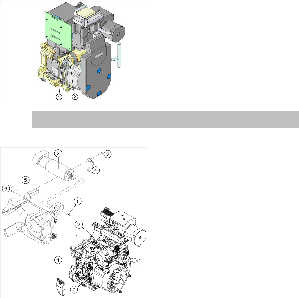
1. Hexagon socket-head screws M3x5 with locking var
-
nish (4x)
2. Z axis drive
3. Hexagon socket-head screws M2.5x12 (2x)
4. Motor clamp upper part /DLM3
5. Motor clamp/DLM3 (do not confuse this with the as
-
sembly clamp for the Z motor tacho interference sup
-
pression board)
6. Hexagon socket-head screws M3x14 (2x)
7. Toothed belt
Service Work
Replacing the Z Axis Drive 3.9.3 Mechanical Adjustment (From Version 03)
44 Service Manual SIPLACE Placement Heads DLM3/DLM4
Installation
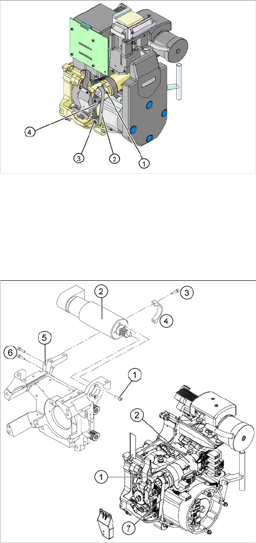
► Further installation is performed by following the above instructions in the reverse order.
► Insert the Z axis drive (2).
► Make sure that the teeth of the toothed belt (7) en
-
gage in the teeth of the motor pinion (1).
► Use the four M3x5 hexagon socket-head screws to fit
the Z axis drive.
► Tension the Z axis toothed belt by moving the Z axis
drive unit upwards and fix the motor with at least one
screw.
► Check the toothed belt tension with the belt tension
measuring device.
Frequency in Hz Before continuous opera
-
tion run
After continuous operation
run
Toothed belt T2 / DLM3 on the Z axis 280 +/- 10 280 +/- 10
► Tighten the two M3x14 hexagon socket-head screws
(6) to fix the motor clamp (5).
► Fix the motor clamp upper part (4) with the two
M2.5x12 hexagon socket-head screws (3).
► Now tighten the hexagon socket-head screws on the
Z axis drive unit and the motor clamp.
► Check the Z axis top stop with the setting gauge.
Service Work
3.9.3 Mechanical Adjustment (From Version 03) Replacing the Z Axis Toothed Belt [00334936-xx]
Service Manual SIPLACE Placement Heads DLM3/DLM4 45
3.12
3.12 Replacing the Z Axis Toothed Belt [00334936-xx]
Replacing the Z Axis Toothed Belt [00334936-xx]
Parts, equipment and tools
▪ Toothed belt T2 /DLM1 [00334936-xx]
Overview
Preparation
► Remove the head from the machine. For details about removing and fitting the placement head, refer
to the service manual for your machine.
Removal
1. Z axis drive stopper
2. Z axis toothed belt
3. Deflection wheel DLM3 (2x)
4. Tension jack (Z axis clamping device)
► Loosen the two screws fastening the tension jack.
► Loosen the two M2.5x12 hexagon socket-head
screws (3) on the motor clamp fitting (4).
► Loosen the two M3x14 hexagon socket-head screws
(6) on the motor clamp fitting (5).
► Slightly loosen the four M3x5 hexagon socket-head
screws (1).
► Remove the toothed belt (7).