00197467-01_SM_DLM3-4_Kunde_en.pdf - 第68页
Settings Setting the Resolution on the Star Axis 68 Service Manual SIPLACE Placement Heads DLM3/DLM4 5.2 5 . 2 S e t t in g t h e R e s o lu t io n o n t h e S t a r A x is Setting the Resolution on the Star Axis 5.3 5 .…

Settings
Overview of Settings
Service Manual SIPLACE Placement Heads DLM3/DLM4 67
5
5 Settings
Settings
5.1
5.1 Overview of Settings
Overview of Settings
Description Tools Values
Replace star motor and/or as
-
sembly assembly of star on star
motor shaft
Adjust magnetic neutral position
with power pack [00353277-xx]
and star zero point gauge and
[03019865-xx]
Check the magnetic neutral posi
-
tion in the station software (max.
deviation 95 digits):
Up to SW60x: in SITEST
From SX70x: in the station soft
-
ware
Determine zero point correction
for the star
Zero point correction gauge
[03019865-xx]
Enter the zero point correction
value determined:
Up to SW60x: with SITEST at
"Positions"
From SW70x: in the station soft
-
ware
Switch position on star motor
(resolution of track signals 10 -
25)
None HF/X/D and DX machines at
Switch setting 25
DP axis incremental encoder ad
-
justment to the glass scale (seg
-
ment)
Test probe 1.4 mm
[00326160-xx]
Test probe 1.5 mm
[00326161-xx]
Test probe 1.6 mm
[00326162-xx]
Distance 1.5 mm
Adjustment of valve positioning
drives from version -03
DLM1: Feeler gauge 0.2 mm
[00325445-xx]
DLM2/3: adjustment plunger for
placement/pickup circuit C&P6/
12 [03066224-xx]
0.2 mm distance plunger to the
valve frame
Light barrier Z axis down Test probes 1.0 mm
[00376656-xx]
Distance 1.0 mm
Z-Axis clamping device --- The tension jack must lie on the
belt teeth at the top and bottom.
Belt tension of the Z axis Belt tension measuring device
(00326015-xx)
Belt tension 280 +/- 5 Hz
Z axis top stop Gauge for Z axis end stopper -
star gauge [03019865-xx]
Correct position is necessary to
determine the zero point correc
-
tion
Blast air tubes on the star Sight check Check: the distance between in
-
cremental encoder and blast air
tubes
Adjustment of blast air supply Feeler gauge Blast air tubes should be approx.
0.7 mm over the frame of the cir
-
cular guide
Adjustment of blast air placement Compressed air testing device
[00311487-xx]
150 mbar on open 9x4 nozzle
Blast air setting on reject circuit
(not for DLM4)
Compressed air testing device
(DLM3) [00311487-xx]
250 mbar
Settings
Setting the Resolution on the Star Axis
68 Service Manual SIPLACE Placement Heads DLM3/DLM4
5.2
5.2 Setting the Resolution on the Star Axis
Setting the Resolution on the Star Axis
5.3
5.3 Setting the Digital Rotary Encoder for the DP Axis
Setting the Digital Rotary Encoder for the DP Axis
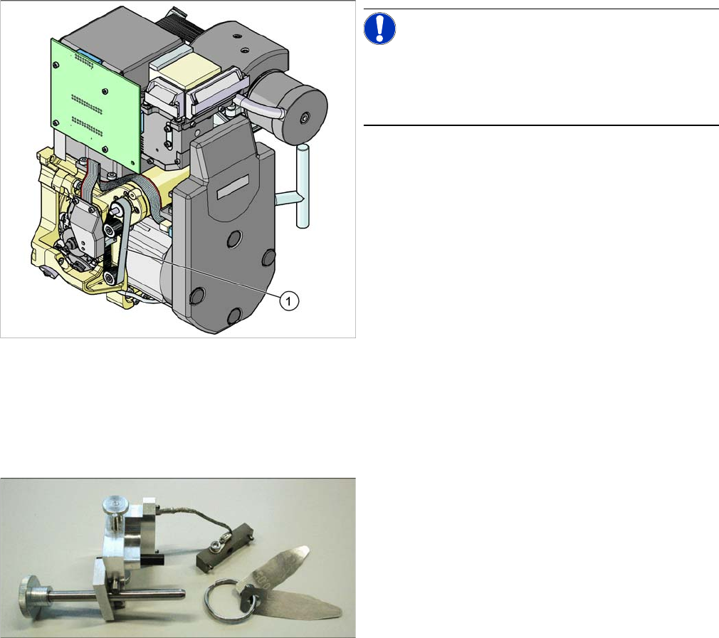
► Remove sleeve 1 and insert the star zero point gauge, in order to mechanically fix the star.
► Now remove sleeve 4 (DLM with 12 segments) or sleeve 2 (DLM with 6 segments) and align the ro
-
tary encoder.
► With the help of a 1.5 mm test probe, set the rotary encoder of the DP axis so that it is parallel to the
glass pane of the segments.
► Perform a check.
Make sure that a 1.4 mm test probe can be easily passed through and that a probe with 1.6 mm can
not be passed through.
Turning station (from version-07)
Belt tension setting for drive belt
replacement
DP belt tensioning device
[03063649-xx]
Achieved with spring tension of
tool
Calibrate DLM head Calibration tool
[03010565-xx]
Achieved with spring tension of
tool
Component sensor assembly
(Option for DLM3)
Assembly gauge
[03003110Sxx]
Assembly gauge provides cor
-
rect position of component sen
-
sor.
Description Tools Values
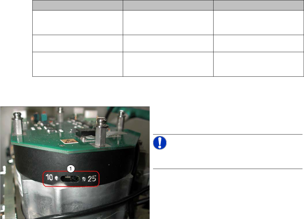
Setting the resolution on the star axis
► Check the switch setting (1) for the star axis resolu
-
tion. This is located directly under the placement
head.
NOTICE!
Only switch the switch setting over when the machine
power is off.
▪ HS-60, HS-50, S-27 HM, S-25 HM, S23 HM: Switch
position 10
▪ D, DX, SX, HF/HF3 and X machines: switch
setting 25
Settings
Setting the Z axis Belt Tension
Service Manual SIPLACE Placement Heads DLM3/DLM4 69
5.4
5.4 Setting the Z axis Belt Tension
Setting the Z axis Belt Tension
5.5
5.5 Adjusting the Stop for the Z Axis
Adjusting the Stop for the Z Axis
Parts, equipment and tools
General
From software version 601.01 onwards, during the reference run, the Z axis moves into the star position
with +/-6250/6750 digits downwards or up into the crank, to determine the Z axis zero point correction
factor. The prerequisite for this is the correct setting of the upper end position stop of the Z axis. This
ensures that the Z axis is in the center of the raceway and that the Z axis zero point can be correctly
determined.
Measurement point for belt tension
NOTICE!
The measurement point should be in the middle, between
two deflection pulleys. The measuring head for the belt
tensioning device should be kept at a distance not ex
-
ceeding 2 - 3 mm to the toothed belt.
► Hold the measuring head of the belt tension measur
-
ing device on the measuring point of the toothed belt
(1).
► Strike the toothed belt, to reach a stimulation of vibra
-
tion of the open ended toothed belt.
► If the belt tension frequency does not match the value
280 Hz ±10 Hz, tension or relax the belt via the drive
motor fastening.
► Repeat these instructions until the belt tension is cor
-
rect.
Gauge for Z end stopper
▪ Set of DIN 911 Allen keys
▪ Gauge for Z axis end stopper - star gauge
[03019865-xx]