00197467-01_SM_DLM3-4_Kunde_en.pdf - 第72页
Settings Determining the Zero Point Correction for the Star Axis of the C&P Head 72 Service Manual SIPLACE Placement Heads DLM3/DLM4 5.7 5 . 7 D e t e r m in in g t h e Z e r o P o in t C o r r e c t io n f o r t h e…
Settings
Setting the Light Barrier Down
Service Manual SIPLACE Placement Heads DLM3/DLM4 71
Setting the Z end stopper
Dismantling the star gauge
5.6
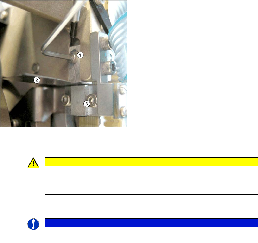
5.6 Setting the Light Barrier Down
Setting the Light Barrier Down
Z end stopper check and adjust
► Loosen the Z axis end stopper screw (1).
► Clamp the 15/100 mm feeler gauge (2) between the
Z end stopper and the tension jack (3). Gently press
the Z axis end stopper downwards with the screwdriv
-
er and screw tight.
⇨ It should now be more difficult to extract the 15/
100 mm feeler gauge.
► Check again whether the 5/100 mm feeler gauge can
be moved easily (without resistance). If this is not the
case, you will need to repeat the adjustment.
CAUTION
Do not damage it
When removing the gauge, make sure that the gauge pin is extracted first and then the star
gauge. If you do not observe this order, the gauge could catch in the segments and damage
these!
NOTICE
Test probe
The light barrier is set with a test probe to a distance of 1.0 mm to the sleeve.
Settings
Determining the Zero Point Correction for the Star Axis of the C&P Head
72 Service Manual SIPLACE Placement Heads DLM3/DLM4
5.7
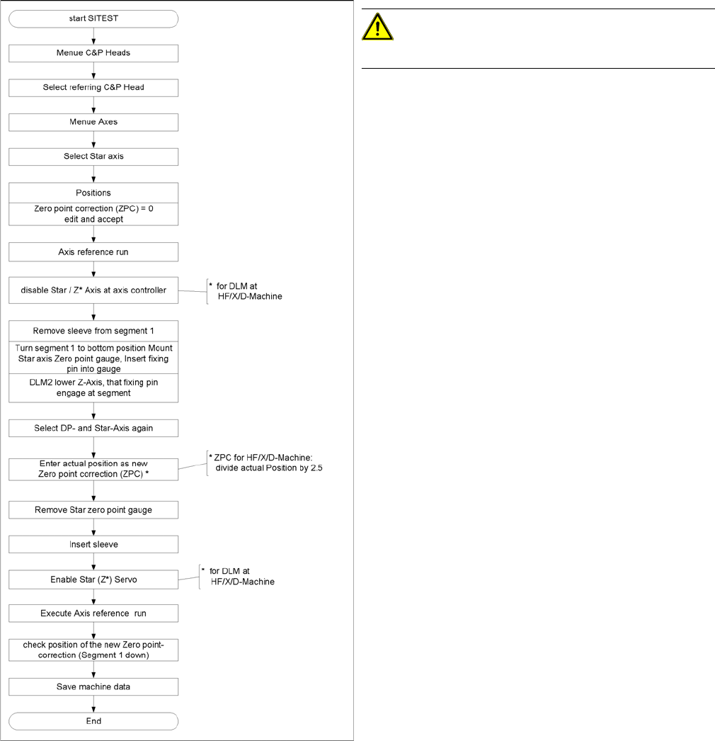
5.7 Determining the Zero Point Correction for the Star Axis of the C&P Head
Determining the Zero Point Correction for the Star Axis of the
C&P Head
Flow chart zero point correction
CAUTION!
When performing this task, follow all instructions exactly!
Settings
Adjustment of air pressure values
Service Manual SIPLACE Placement Heads DLM3/DLM4 73
5.8
5.8 Adjustment of air pressure values
Adjustment of air pressure values
Tools and equipment
▪ A set of slotted screw drivers
▪ Compressed air testing device
Setting the Blast Air Pressure Values
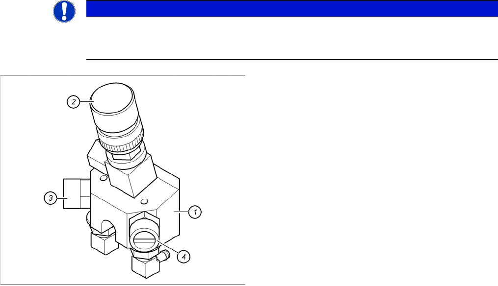
NOTICE
DLM4 head
The DLM4 head adjustment is carried out only for pick-up/placement circuit. The air regulator
of the forced air valve for reject circuit is not in use and must be closed.
Adjustment of air pressure values
1. Forced air unit
2. Micro-relay valve
3. Air regulator for the reject circuit
4. Air regulator for the pick-up/placement circuit
► Use the following nozzle type to set the blast air
DLM3: 914
DLM4: 3004 or 3014
► Please press in the spring from the nozzle interface
during the measurement and read the value from the
display.