00197467-01_SM_DLM3-4_Kunde_en.pdf - 第74页
Settings Adjustment of air pressure values 74 Service Manual SIPLACE Placement Heads DLM3/DLM4 Setting the blast air pressure values with the compressed air t esting device Adjust to the values of the table below: Repeat…
Settings
Adjustment of air pressure values
Service Manual SIPLACE Placement Heads DLM3/DLM4 73
5.8
5.8 Adjustment of air pressure values
Adjustment of air pressure values
Tools and equipment
▪ A set of slotted screw drivers
▪ Compressed air testing device
Setting the Blast Air Pressure Values
NOTICE
DLM4 head
The DLM4 head adjustment is carried out only for pick-up/placement circuit. The air regulator
of the forced air valve for reject circuit is not in use and must be closed.
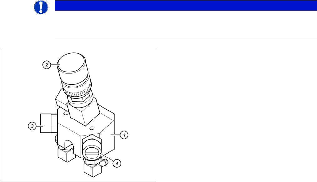
Adjustment of air pressure values
1. Forced air unit
2. Micro-relay valve
3. Air regulator for the reject circuit
4. Air regulator for the pick-up/placement circuit
► Use the following nozzle type to set the blast air
DLM3: 914
DLM4: 3004 or 3014
► Please press in the spring from the nozzle interface
during the measurement and read the value from the
display.
Settings
Adjustment of air pressure values
74 Service Manual SIPLACE Placement Heads DLM3/DLM4
Setting the blast air pressure values with the compressed air testing device
Adjust to the values of the table below:
Repeat these adjustments several times, as the pickup/placement and reject circuits are mutually de
-
pendent.
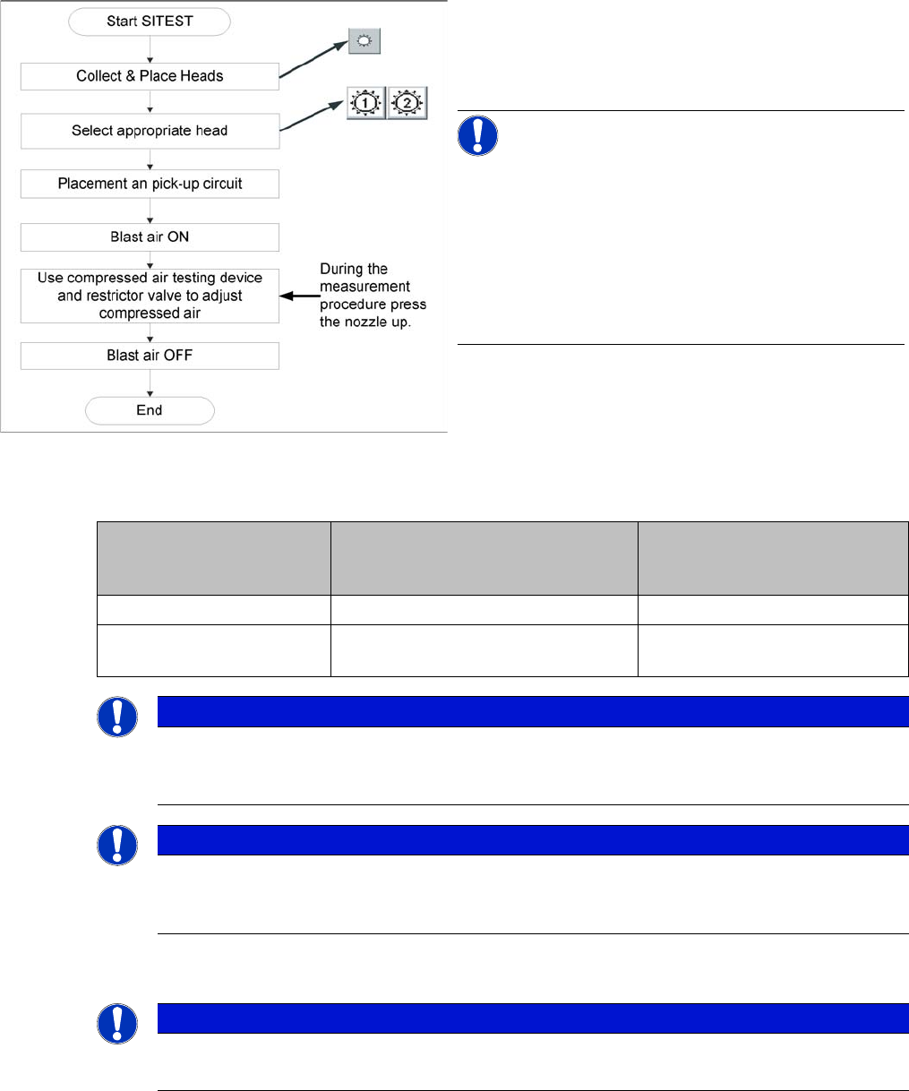
Flow chart determining air pressure values
When setting the blast air value with the compressed air
device and the air regulator, observe the following:
► Press the nozzle upwards during the measurement
process!!
NOTICE!
The blast air values shown in the "Measure blast air pres
-
sure" menu item at the screen of the station computer in
"Manual Operations" or in the SITEST program, do not
reflect the blast air values really set at the nozzle. They
are only for checking that the blast air valve is functioning
correctly. Therefore, do not use the values shown on the
screen to set the blast air. Instead, use only the values
determined with the compressed air testing device.
Air pressure values Set with compressed air testing de
-
vice
Measured at nozzle
Shown on monitor
(Only in pickup and placement
circuit)
Pickup/placement circuit 150 mbar (100 - 200 mbar) e. g.: 250 mbar
Reject circuit 250 mbar (200 - 300 mbar) Reject circuit does not have a
sensor
NOTICE
Adjustment of reject circuit not required
Reject circuit settings are not necessary for HF/X machines.
The air regulator of the reject circuit is closed for DLM4 heads.
NOTICE
Blast air circuits
The two blast air circuits are controlled via a single valve and therefore influence one another
mutually. However, the two air regulators can be used to set different pressures for each circuit.
NOTICE
Measuring sensor hose
Make sure the measurement sensor hose is fitted tightly on the nozzle.
Settings
Vacuum Test
Service Manual SIPLACE Placement Heads DLM3/DLM4 75
5.9
5.9 Vacuum Test
Vacuum Test
Damage to the valve plunger, silicone hose, the vacuum plate, in or on the nozzle can lead to leakage
which may then cause malfunctions during the placement process or which may reduce the vacuum val
-
ue in the holding circuit.
Parts, equipment and tools
Vacuum test
Equipment required
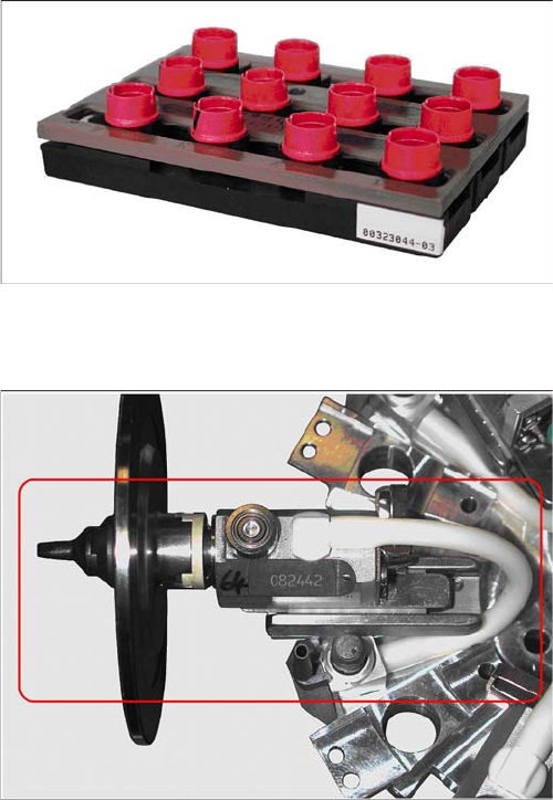
Closed nozzle tips are required for checking the complete
vacuum circuit.
The special nozzle use for this is marked red and does
not have a nozzle configuration on it:
▪ SOKO nozzle for vacuum test DLM [03067029
-
xx]
Vacuum test with normal nozzle configuration
▪ The vacuum tests in the station software only check
the area from the vacuum generator to the valve
plungers.
▪ The area visible here (red frame), from the valve
plunger housing via the silicone hose into the seg
-
ment housing and through the sleeve to the nozzle is
not covered by the normal vacuum test.