00197467-01_SM_DLM3-4_Kunde_en.pdf - 第79页
Settings Firmware Download (SW 70x) Service Manual SIPLACE Placement Heads DLM3/DLM4 79 5.12 5 . 1 2 F ir m w a r e D o w n lo a d ( S W 7 0 x ) Firmware Download (SW 70x) ► The function Firmware Download can be perfor m…
Settings
DLM4 Assembly with adapter plate
78 Service Manual SIPLACE Placement Heads DLM3/DLM4
5.10
5.10 DLM4 Assembly with adapter plate
DLM4 Assembly with adapter plate
The screws fastening the DLM4 head must be tightened with a torque of 2.7 Nm to the adapter plate.
The screws fastening the adapter plate must be tightened with a torque of 2.7 Nm to the head mounting
plate of the gantry.
5.11
5.11 Other Mechanical Settings on the Star
Other Mechanical Settings on the Star
▪ Set the blast air tube so that it overlaps the circular guide frame by 0.7 mm.
NOTICE
Replacing the DLM4 head
The DLM4 head can be replaced as part of service work.
► If the DLM4 head is fixed to an adapter plate, this will need to be taken off the old head and
fitted to the new one.
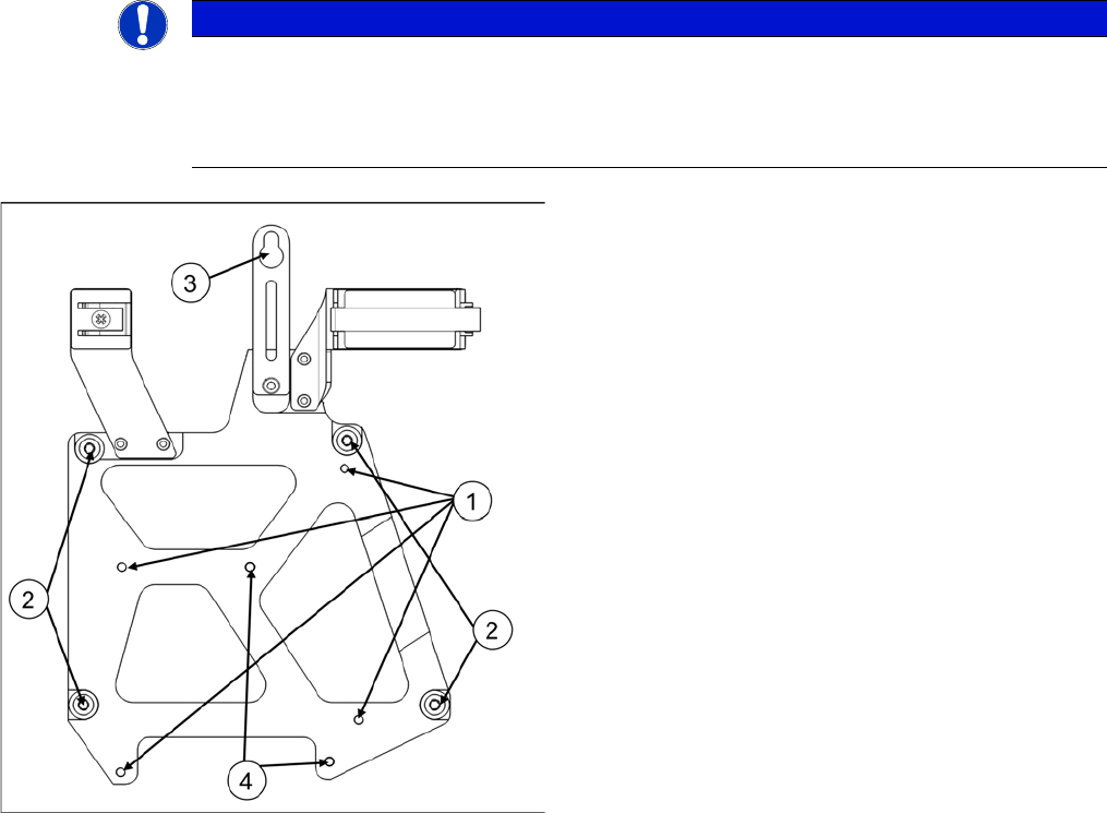
Adapter plate DLM4
The adapter plate hardware is designed for quick head
replacement (e.g. for maintenance). It has captive screws
and an eyelet for initial fixation of the head to the head
mounting plate of the gantry.
1. Fastening for DLM4 head on the adapter plate
2. Fastening for adapter plate on the gantry head carrier
3. Loop for fast head exchange (FHE)
4. Centering pins for the DLM4 head
Settings
Firmware Download (SW 70x)
Service Manual SIPLACE Placement Heads DLM3/DLM4 79
5.12
5.12 Firmware Download (SW 70x)
Firmware Download (SW 70x)
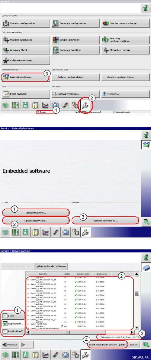
► The function Firmware Download can be performed
with the operator levels (1) Machine-Service or
SIPLACE-Service.
► Switch over to the service menu (2).
► Select the button Embedded Software (3).
► (1) Select this button to check the entire machine and
to perform an eSW download for multiple subsys
-
tems.
► (2) Select this button to select and check one subsys
-
tem, to perform an eSW download.
► (3) Select this button to view all versions of the sub
-
systems, BIOS application 1/2.
1. Selection button, BIOS application 1/2
2. Shows the status of the individual subsystems.
3. Update information about the number of subsystems
which still have to be downloaded.
4. Starts the download.
Settings
Calibration 5.13.1 Calibrating the Heads and Cameras (SW60x)
80 Service Manual SIPLACE Placement Heads DLM3/DLM4
5.13
5.13 Calibration
Calibration
Overview
This calibration step first measures the component camera. This determines the relationship of "camera
pixel size to resolution of machine measuring system (X,Y)", the "camera center point in X and Y direc
-
tion" and the "torsion angle of the CCD sensor in the camera". This is following by determining the head
offset and the segment offsets for the top and bottom.
▪ Head offset: the head offset is the distance between the PCB camera and the nozzle (segment 1).
The target is a fixed value (X=0 and Y=
-
105 mm), to which an offset value (from the head calibration)
is added.
▪ Segment offset top: the top segment offset involves turning the calibration tool in the component
camera in 0, 90, 180 and 270° steps. The value determined is that of the rotating center of the nozzle
tip in relation to the component camera center in the X and Y direction.
▪ Segment offset bottom: the bottom segment offset involves recording and measuring the calibration
tool in the 0, 90, 180 and 270° positions. The value determined is that of the rotating center point of
the nozzle tip when the Z axis is extended in relation to the PCB camera. Segment 1 forms the ref
-
erence (X=0, Y=0) to the other segments.
5.13.1
5.13.1 Calibrating the Heads and Cameras (SW60x)
Calibrating the Heads and Cameras (SW60x)
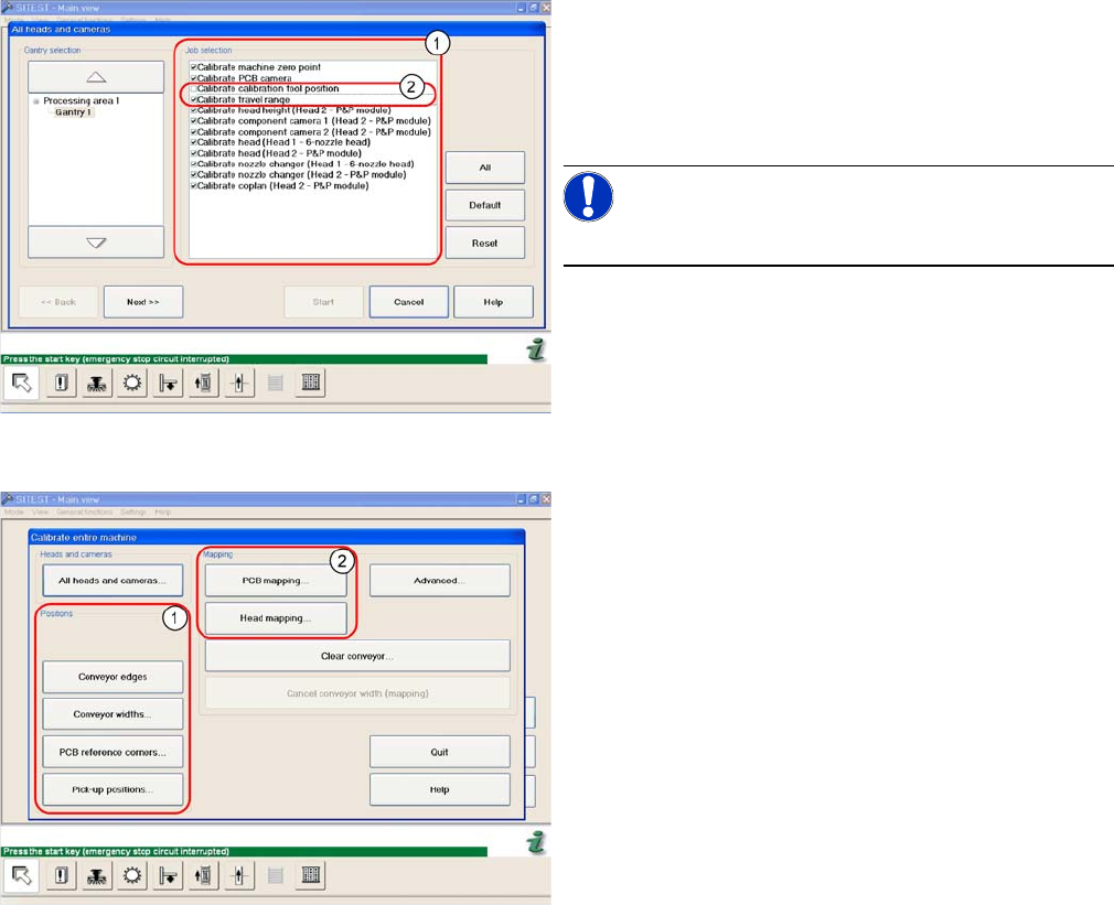
Automatic calibration of all heads and cameras
The menu may vary, according to the machine type and
configuration.
► Go to SITEST and select Calibrate Entire Machine --
> All Heads and Cameras to access the adjacent
menu.
► Go to the section Job Selection (1) and select the
components to be calibrated.
NOTICE!
These two entries (2) are optional.
► To continue calibration with manual handling, select
the four consecutive menus in from the section Posi
-
tions (1) and the two menu items from the section
Mapping (2).