00197467-01_SM_DLM3-4_Kunde_en.pdf - 第85页
Description of the Circuit Boards SP_12 Digital Intermediate Distributor [00330648-05] Service Manual SIPLACE Placement Heads DLM3/DLM4 85 6.2 6 . 2 S P _ 1 2 D ig it a l I n t e r m e d ia t e D is t r ib u t o r [ 0 0 …
Description of the Circuit Boards
Base adapter DLM [03081413-xx]
84 Service Manual SIPLACE Placement Heads DLM3/DLM4
7-segment display H11 [03081413-03]
7-segment display H12 [03081413-03]
7-segment display H13 [03081413-03]
Dip switch S1 [03081413-03]
H20 RD - BAS ERR Not used:
Overcurrent, "Placement/pick-up station"
stepping motor
H21 GN - - Not used
H22 GN ON Z D „Z axis bottom“ light barrier activated
H23 GN ON Z-U „Z axis top“ light barrier activated
H24 GN ON DZS INT „Swivel in DP drive“ stepping motor
H25 GN ON ZHS INT "Pick-up/placement circuit" stepping motor,
light barrier activated
H26 GN ON BAS_INT Stepping motor for "Reject" valve drive
Display Status Description
Decimal point Flashes HCU2 OK
Display Status Description
Decimal point Flashes X167 OK
Display Status Description
Decimal point Flashes HCU1 OK
Switch Status Signal name Description
S1.1 OFF HCU_CM_FPGA_IO_2 „S0“ (gantry coding), not used
S1.2 OFF HCU_CM_FPGA_IO_3 „S1“ (gantry coding), not used
S1.3 OFF HCU1_RESET_N „R_HCU1“, ON: Reset HCU1
S1.4 OFF HCU2_RESET_N „R_HCU2“, ON: Reset HCU2
S1.5 OFF RSINS „R_X167“, ON: Reset TQ module
S1.6 OFF HCU_COM_BOOT_N „B_HCUX“, ON: set HCU to boot mode
S1.7 OFF BOOTSTR „B_XC167“, ON: set TQ module to boot
mode
S1.8 - - „FREE“, not used
LED Color Status Signal name Description
Description of the Circuit Boards
SP_12 Digital Intermediate Distributor [00330648-05]
Service Manual SIPLACE Placement Heads DLM3/DLM4 85
6.2
6.2 SP_12 Digital Intermediate Distributor [00330648-05]
SP_12 Digital Intermediate Distributor [00330648-05]
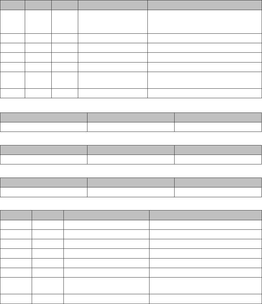
The intermediate distributor (1) is fixed to the front part (6) with four spacer bolts (items 2, 3, 4 and 5).
The cover of the intermediate distributor is fixed with push buttons.
Two 40-pin flat ribbon cables run from plug X1 and X2 on the intermediate distributor to socket X14 / X13
on the head board.
Intermediate distributor
1. Intermediate distributor
2. Spacer bolt M3x10
3. Spacer bolt M3x10
4. Spacer bolt M3x10
5. Spacer bolt M3x10
6. Front section of C&P
7. Connectors X1 and X2 (on the rear side)
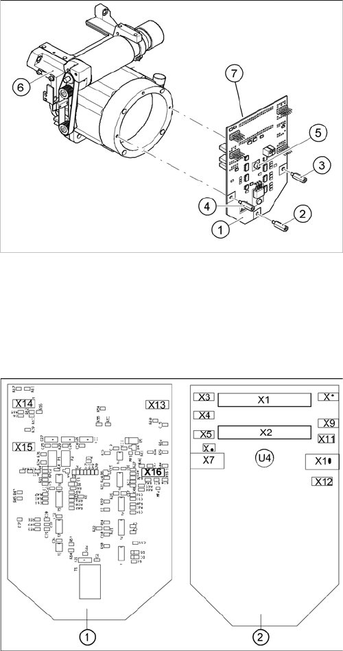
Position of the sockets
1. Front of the intermediate distributor
2. Back of the intermediate distributor
U4 = pressure sensor

Description of the Circuit Boards
SP_12 Digital Intermediate Distributor [00330648-05]
86 Service Manual SIPLACE Placement Heads DLM3/DLM4
The following supply voltages and signals are routed by the intermediate distributor to the individual
placement head modules or to the head board:
Connectors Description
X1, 40-pin Connected to plug X14 on the head board
▪ Voltage supply, tacho and track signals for the Z axis drive
▪ Signal from light barrier "Z axis in top position"
▪ Signal from light barrier "Z axis in bottom position" (sensor stop signal)
▪ Control signal for the blast air valve
▪ Supply voltage +5 VDC, ±15 VDC
▪ Reference point signal for the DP axis
▪ Track signals for the DP axis
X2, 40-pin Connected to plug X13 on the head board
▪ Voltage supply and track signals for the star axis drive
▪ Reference point for the star axis
▪ Analog blast air pressure value
▪ Supply voltages +5 VDC, ±15 VDC, +24 VDC
X3, 10-pin Connection for the Z motor and Z tacho signal (Tacho signal is not use on
the HF machine)
X4, 10-pin Connection for the Z axis track signals
X5, 10-pin Connection for the star motor
X6, 6-pin Connection for the blast air valve
X7, 10-pin Connection for the DP axis track signals
X10, 10-pin Connection for the "Z axis up" signal (positioning unit)
X11, 8-pin Connection for the light barrier "Z axis down" signal (sensor stop signal)
X12, 10-pin Connection for the star axis track signals
X13, 10-pin Test connection for the Z axis track signals
X14, 10-pin not used
X15, 10-pin Test connection for the star axis track signals
X16, 10-pin Test connection for the DP axis track signals