00197467-01_SM_DLM3-4_Kunde_en.pdf - 第86页
Description of the Circuit Boards SP_12 Digital Intermediate Distributor [00330648-05] 86 Service Manual SIPLACE Placement Heads DLM3/DLM4 The following supply voltages and signals are ro uted by the int ermediate distr …
Description of the Circuit Boards
SP_12 Digital Intermediate Distributor [00330648-05]
Service Manual SIPLACE Placement Heads DLM3/DLM4 85
6.2
6.2 SP_12 Digital Intermediate Distributor [00330648-05]
SP_12 Digital Intermediate Distributor [00330648-05]
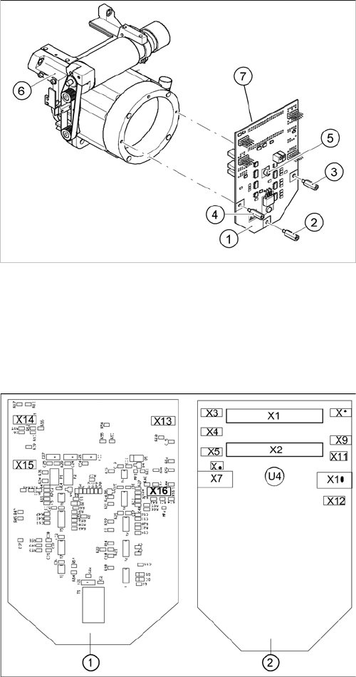
The intermediate distributor (1) is fixed to the front part (6) with four spacer bolts (items 2, 3, 4 and 5).
The cover of the intermediate distributor is fixed with push buttons.
Two 40-pin flat ribbon cables run from plug X1 and X2 on the intermediate distributor to socket X14 / X13
on the head board.
Intermediate distributor
1. Intermediate distributor
2. Spacer bolt M3x10
3. Spacer bolt M3x10
4. Spacer bolt M3x10
5. Spacer bolt M3x10
6. Front section of C&P
7. Connectors X1 and X2 (on the rear side)
Position of the sockets
1. Front of the intermediate distributor
2. Back of the intermediate distributor
U4 = pressure sensor

Description of the Circuit Boards
SP_12 Digital Intermediate Distributor [00330648-05]
86 Service Manual SIPLACE Placement Heads DLM3/DLM4
The following supply voltages and signals are routed by the intermediate distributor to the individual
placement head modules or to the head board:
Connectors Description
X1, 40-pin Connected to plug X14 on the head board
▪ Voltage supply, tacho and track signals for the Z axis drive
▪ Signal from light barrier "Z axis in top position"
▪ Signal from light barrier "Z axis in bottom position" (sensor stop signal)
▪ Control signal for the blast air valve
▪ Supply voltage +5 VDC, ±15 VDC
▪ Reference point signal for the DP axis
▪ Track signals for the DP axis
X2, 40-pin Connected to plug X13 on the head board
▪ Voltage supply and track signals for the star axis drive
▪ Reference point for the star axis
▪ Analog blast air pressure value
▪ Supply voltages +5 VDC, ±15 VDC, +24 VDC
X3, 10-pin Connection for the Z motor and Z tacho signal (Tacho signal is not use on
the HF machine)
X4, 10-pin Connection for the Z axis track signals
X5, 10-pin Connection for the star motor
X6, 6-pin Connection for the blast air valve
X7, 10-pin Connection for the DP axis track signals
X10, 10-pin Connection for the "Z axis up" signal (positioning unit)
X11, 8-pin Connection for the light barrier "Z axis down" signal (sensor stop signal)
X12, 10-pin Connection for the star axis track signals
X13, 10-pin Test connection for the Z axis track signals
X14, 10-pin not used
X15, 10-pin Test connection for the star axis track signals
X16, 10-pin Test connection for the DP axis track signals
acpage