00193697-01.pdf - 第46页
3 Graphical user int erface SIPLACE Softw are Guide SR.504.xx 3.3 User interf ace - views and menus Issue 01/03 EN 46 3.3.2.5 "Language " menu It is pos sible to set the la nguage versio ns for th e user i nter…
SIPLACE Software Guide SR.504.xx 3 Graphical user interface
Issue 01/03 EN 3.3 User interface - views and menus
45
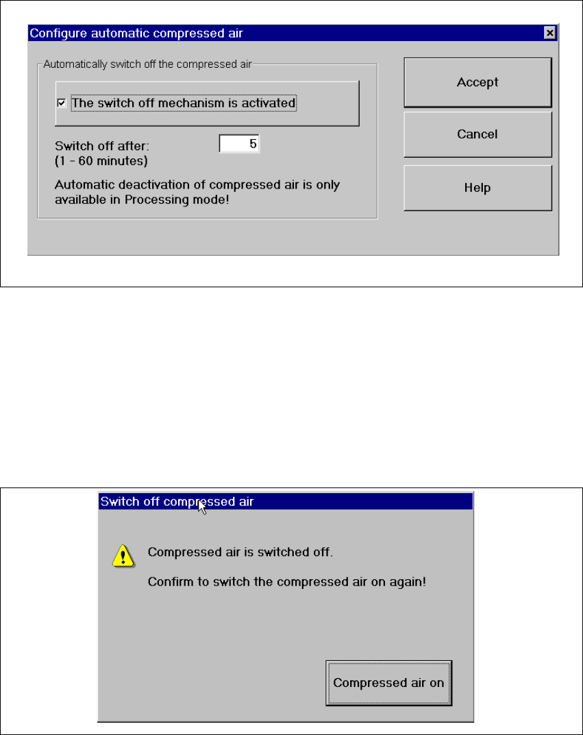
Å Click the Configure compressed air deactivation... menu item.
This displays the following window.
3
Fig. 3.3 - 16 "Configure compressed air deactivation" dialog box
Å Activate/deactivate the check box for the automatic deactivation.
Å Click Accept to save the settings.
3
Å Click the Switch off compressed air... menu item. (This function is only possible if the ma-
chine is in the "Processing suspended" status.)
This displays the following window.
3
Fig. 3.3 - 17 "Switch off compressed air" window
Å Activate the Compressed air on button.
Å The compressed air is reactivated.

3 Graphical user interface SIPLACE Software Guide SR.504.xx
3.3 User interface - views and menus Issue 01/03 EN
46
3.3.2.5 "Language" menu
It is possible to set the language versions for the user interface integrated into the station com-
puter software via the "Language" menu.
The user interface can be changed to a different language from any view.
You can choose between "German" and "English". 3
Å Click the menu item corresponding to the required language.
The user interface texts are displayed in the selected language.
Å It is possible to extend the range of languages available using a language CD to install addi-
tional languages.
3.3.2.6 "Help" menu
This menu gives you access to all the functions required to call the help system as well as general
information concerning the station computer or the software. 3
Contents Ctrl+F1 3
This calls the online Help system. 3
Help Alt+F1 3
This calls the Help system and displays information about the current view. 3
Use help 3
Information on how to use the Help system is displayed. 3
Info... 3
This displays information on the currently installed software version (SC version), the service
pack, the language CD and general information on the station computer. 3
NOTE
You can use the button (bottom right) to call the online Help system from within any view of
the user interface.
This calls the help system for the current view.
A detailed description of the functions in the Help menu can be found in Chapter 6. 3
Å Click the required menu item in the "Help" menu or press the corresponding key combination.
3
SIPLACE Software Guide SR.504.xx 3 Graphical user interface
Issue 01/03 EN 3.4 Flow chart for the main view
47
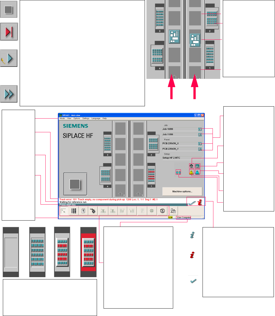
3.4 Flow chart for the main view
3
3
3
Pull-down menus
3
Error information
bar
3
Status indication
and process status
3
Notification about a
specific action to
carry out
3
Information bar
3
Control modes:
Stand alone
SIPLACE Pro
3
Submenu icons with info box:
Main view
Setup
Error
Feeders
Gantry 1, 2
PCB conveyor 2, 1
Teach fiducial
Test component
SITEST
GEM
3
Output conveyor
The output conveyor is empty.
MTC on location 2
Central conveyor
The PCB is supplied.
Input conveyor
The input conveyor is empty.
3
Context-sensitive help system
This also provides a short description of all
displayed operating elements.
3
Help system for errors
Starts a help system displaying possible
causes of the current error along with correc-
tive actions.
3
Error deletion
After the error has been successfully cor-
rected, the currently active error is deleted.
Transport 2
Transport 1
3
Identifies the job or panel of the
right conveyor lane, or of the
single conveyor, and of the left
conveyor lane (dual conveyors
only).
3
Barcode-supported component
refilling
3
PCB barcode is activated.
3
Machine options have been
changed
3
Software options configured
3
Compressed air switch-off
mechanism configured
1234
1 No setup available on the corresponding location
2 Setup available
3 Setup available - at least one empty track error
4 Machine standstill due to track error
3
This display appears during the start-up process of the machine. Only when the
reference run has been completed successfully will the display appear in the form
of a button.
3
Status
The machine is running, or is in its 'ready' state.
Pressing the button:
The machine stops.
3
Status
The machine is placing components; 'stop' is activated. The assembly of the
PCBs located in processing conveyors 1 and 2 or in the central conveyor will be
terminated and the PCBs will be transported to the intermediate or output
conveyor. Subsequently, the machine will stop.
Pressing the button:
The machine continues to run without interruption.
3
Status
Machine is in the stopped state.
Pressing the button:
The machine resumes the placement operation.