00193697-01.pdf - 第97页
SIPLACE S oftware Guide SR.504.xx 8 New functionality in 504.01 Issue 01/03 E N 8.15 OIS 97 8.15 O IS The so ftwa re vers ion OIS 2.2 supp ort s the S IPLACE H F machi ne. 8 NOTE A detailed de scrip tion of the so ftware…
8 New functionality in 504.01 SIPLACE Software Guide SR.504.xx
8.12 CAN interface modules Issue 01/03 EN
96
8.12 CAN interface modules
The CAN interface modules have been enhanced to include the following features: 8
– baud rate setting
– CAN-ID allocation
– Support for the platform III protocol
8.13 CAN/axis driver
The axis driver in the machine controller is responsible for communication with the axes. In the
SIPLACE HF, this interface has been changed from an SMP bus to a CAN bus. The protocol used
is the platform III protocol for subsystems on the CAN bus. 8
This means that no extra software version needs to be created in the axis firmware in order to map
the previous platform II protocol from the SDP bus to the CAN bus. The switch to CAN bus
interface means that the data structure of the axis firmware is also changed. 8
8.14 Barcode reader
8.14.1 Component barcode reader
In version 504 of the software you can use both the existing cabled barcode reader which is part
of component verification system or the SIPLACE Mobile Verifier (SMV). 8
Component verification can be called with View--> Setup. 8
8.14.2 PCB barcode reader
In version 504 of the software, both the existing barcode reader as well as the 2D barcode reader
can be used. 8
The dialog box "PCB barcode" can be called with Options --> PCB barcode.... 8
SIPLACE Software Guide SR.504.xx 8 New functionality in 504.01
Issue 01/03 EN 8.15 OIS
97
8.15 OIS
The software version OIS 2.2 supports the SIPLACE HF machine. 8
NOTE
A detailed description of the software option OIS 2.2 can be found in the instructions "Getting
started with OIS 2.2“ and the OIS 2.2 online Help system. 8
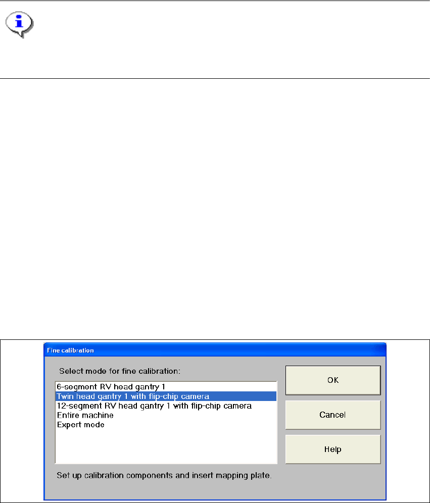
8.16 Fine calibration
The functionality has been enhanced compared with version 502 of the software and covers the
following Twin Head features: 8
– Placing and measuring an entire Twin Head panel (24 components per segment)
– Placing and measuring a single Twin Head segment panel (48 components per segment)
– A combination of the two scenarios above with any stationary component camera
– Recording and incorporation of segment-specific offsets for the Twin Head
– Used IC camera CC02-05, FC camera CC07-500
Fine calibration can be called with Options--> Fine calibration mode.... 8
8
Fig. 8.16 - 1 "Fine calibration" dialog box
8 New functionality in 504.01 SIPLACE Software Guide SR.504.xx
8.17 FiFo option for each location Issue 01/03 EN
98
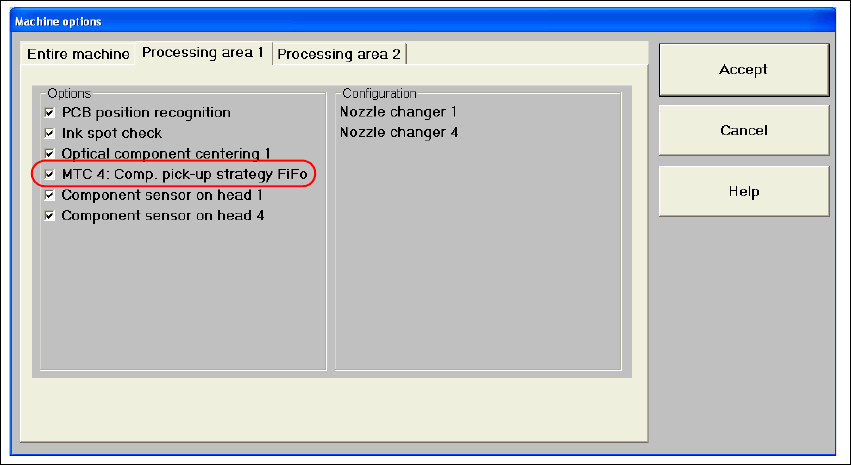
8.17 FiFo option for each location
If an MTC is attached to the machine, the FiFo pickup strategy may or may not be used to pick up
components (First in First out: The first components stored in the MTC are the first components
to be placed). In the past (version 502 of the software), this setting applied to the entire machine.
Thus, the machine option setting applied to all MTCs attached to a given machine. 8
As of version 504 of the software, this option can be activated on a location-by-location basis on
a SIPLACE HF with MTC 2. The FiFo option now appears in the machine options for the various
processing areas depending whether an MTC is attached. 8
The Machine options dialog box can show up to 4 options (for a SIPLACE HF only locations 2
and 4: 8
– MTC 1: Component pickup strategy: FiFo
– MTC 2: Component pickup strategy: FiFo
– MTC 3: Component pickup strategy: FiFo
– MTC 4: Component pickup strategy: FiFo
8
Fig. 8.17 - 1 FiFo machine options
The options are only visible if an MTC is attached. 8
8