00196371-0102_ AI_Kopfständer_ DE+EN.pdf - 第12页
12 1.2 General This document describes th e assembly and folding of the head mount an d the installa tion of the placement heads on the head st and. The head st and was develo ped primarily for the m aintenance of the pl…

Universal Head Stand item no. 03056231-01
Ausgabe 04/2008 Edition
11
1 Universal Head Stand item no. 03056231-01
1.1 Safety instructions
WARNING:
Comply with the higher ranking "Safety Instructions" in Chapter "Operational Safety" in the User
Manual and Service Manual.
The placement machines SIPLACE are powered by mains voltage.
Portions of the system are therefore conducting dangerous electricity, inside the machine even
while the master switch is turned off.
Death, serious injury or considerable damage may result if these automatic placement systems
are handled incorrectly.
After you have properly carried out the shut-down of the operating system:
Before all work the machine must be turned off at the main switch and isolated from the mains. In
addition, the compressed air supply must be turned off at the main valve of the compressed air
unit in the machine base.
Danger:
For anyone wearing a heart pacemaker it is not permitted to work near linear motors, as described
in detail in the User Manual and the Service Manual, Chapter "Special Safety Instructions when
working in vivinty of powerful magnetic fields" .
Obey the applicable accident prevention regulations, DIN standards and special safety codes of
your country at all times. DIN EN 60204 must be adhered to during all work inside the machine
base.
Follow the instructions regarding residual voltages in Chapter "Operational Safety".
Comply with regulations on ESDs (see Chapter "Operational Safety").
During the work of service secure the machine conscientiously against other personnel and pre-
vent it from being turned back on without authorization, as described in the User Manual in the
chapter "Locking the Machine...".
There is additional, higher risk of accident when working with the SITEST program.
The SITEST program is only to be started by personnel who are authorized to do so.
12
1.2 General
This document describes the assembly and folding of the head mount and the installation of the
placement heads on the head stand.
The head stand was developed primarily for the maintenance of the placement heads C&P20 and
C&P20A.
Furthermore the following placement heads can be installed on the head stand:
- Pick&Place module (Twin Head)
- C&P 6/12 DLM 2 and DLM3
- C&P20, C&P20 A
- CPP
- IC Head
- C&P6/12 DLM1 resp. 10000 series (only with restrictions)
fig. 1.2 - 1 Universal head stand - folded together
Universal Head Stand item no. 03056231-01
Ausgabe 04/2008 Edition
13
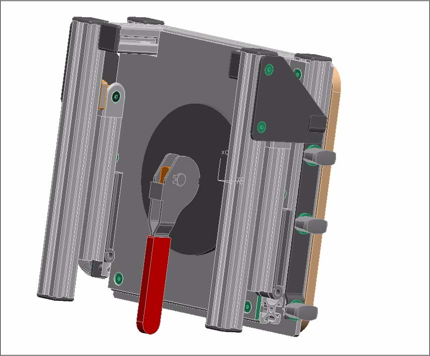
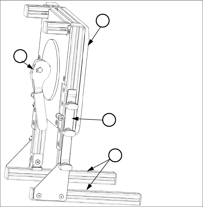
1.3 Design und function of the head stand
The head stand consists of a foldable frame (1) and a turnable head mounting plate (2). After the
assembly of the head mount the placement head can be installed in "zero degree position". The
head can be turned in the desired position and is fixed by means of the red lever (3).
(1) foldable frame (2) head mounting plate
(3) red lever - fixing the head mounting plate (4) locking rail with mounting bolts
3
2
1
4