00196371-0102_ AI_Kopfständer_ DE+EN.pdf - 第15页
Universal Head Stand item no. 03056231-01 Ausgabe 04/2008 Edition 15 1.3.2 Folding the head stand Æ Put the head stand with the mounting plate down onto an even table (1) . Æ Losen all 6 and move the locking ra ils (2) b…
14
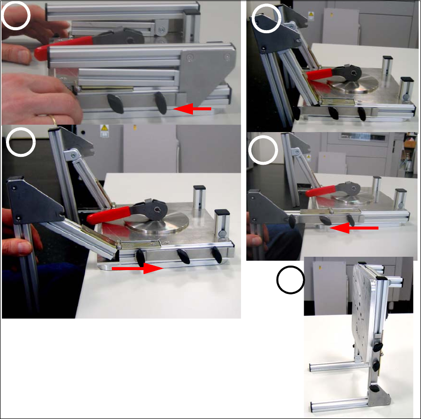
1.3.1 Assembly of the head
Æ Put the head stand with the mounting plate down onto an even table.
Æ Losen the screws (1) on the left and the right side - 3 screws on each side.
Æ Move the left and the right locking rail (2) forward.
Æ Unfold the two feet of the head stand (2).
Æ Attention: Don’t push the feet of the head stand downward!
Æ Move the locking rail backward again in order to unfold the head stand comple.(3)
Æ Now move the locking rail forward so that the mounting screws lock into the notch (4).
Æ Fix the screws easily and put the head stand onto the table.
Æ Align both feet of the head stand so that the head stand doesn’t tilt and tighten all 6 mounting
screws (5).
fig. 1.3 - 1 Sequence of the head stand assembly
1
3
2
4
5
Universal Head Stand item no. 03056231-01
Ausgabe 04/2008 Edition
15
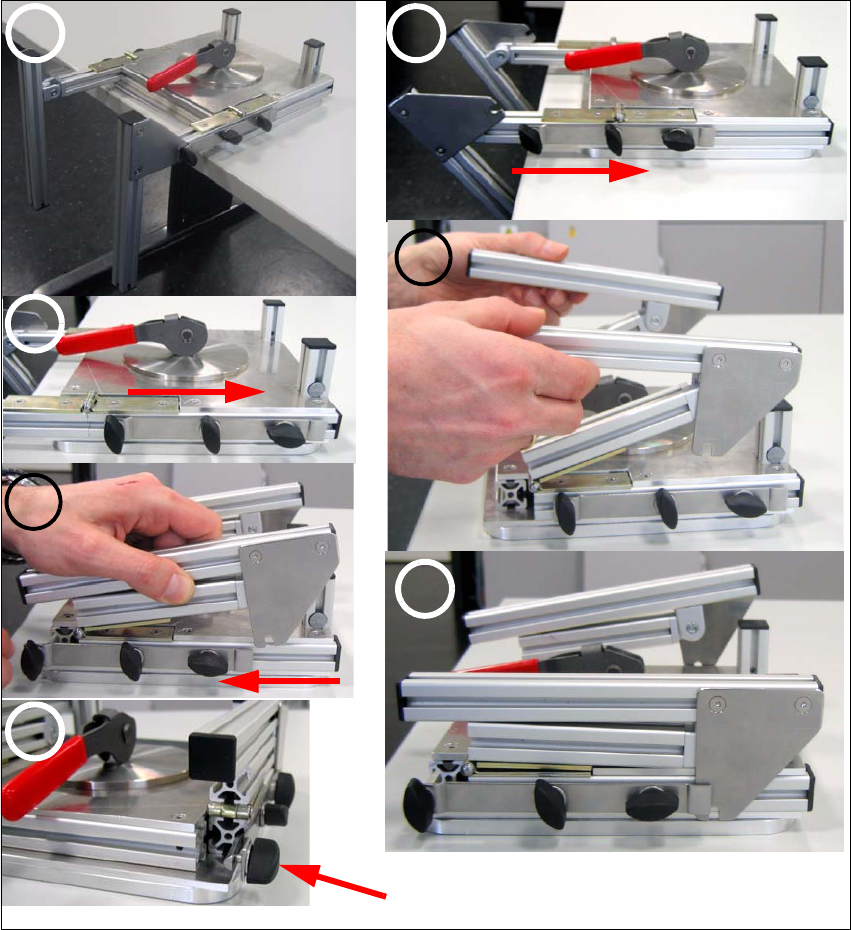
1.3.2 Folding the head stand
Æ Put the head stand with the mounting plate down onto an even table(1).
Æ Losen all 6 and move the locking rails (2) backward so that the head stand can be folded.
Æ Now fold the feet of the head stand (4).
Æ Move the locking rails forward so that the feet of the head mount lay on the frame of the moun-
ting plate (5).
Æ Now move the locking rail over the metal plate and fix all mounting screws (6).
fig. 1.3 - 2 Folding the head stand
1 2
3
4
5
6
7
Attention! Fix this screw easily only.
16
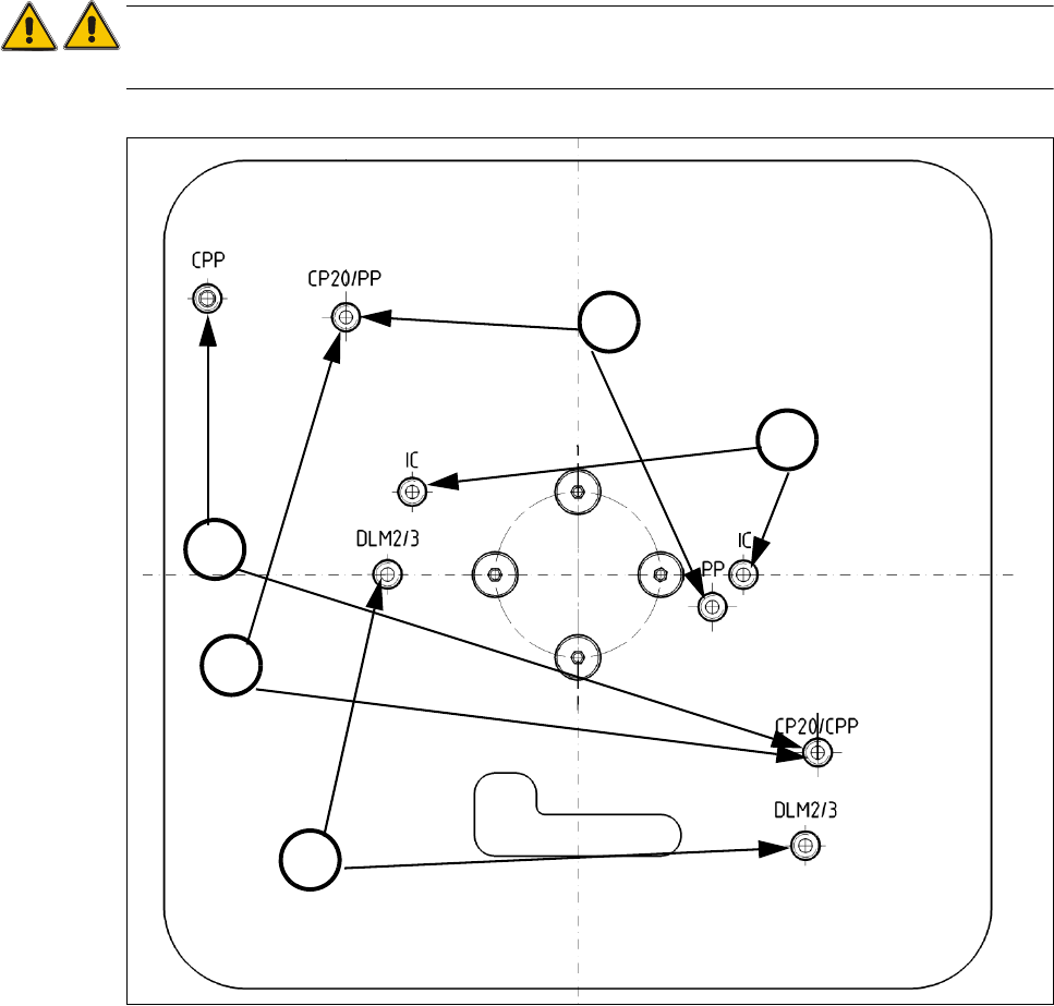
1.3.3 Mounting plate
The turnable mounting plate allows maintenance and service work on all placement heads. The
placement heads are fixed with two mounting screws.
ATTENTION
Only use original mounting screws the installation..
.
fig. 1.3 - 3 Fixation on mounting plate
(1) Fixation of C&P20 / C&P20A (2) Fixation of CPP Head
(3) IC Head (4) Pick&Place module (Twin Head)
(5) Fixation of C&P6712 DLM2/3
2
3
4
1
5