Maintenance Reference(CP45FV) Eng.pdf - 第124页
Samsung Component Placer CP45FV Series Maintenance Guide Corrective measures Cause Corrective measures 1 The value of system parameter is outside the setting range. Check servo amplifier model. Check the setting value of…
Inspection of the Controller
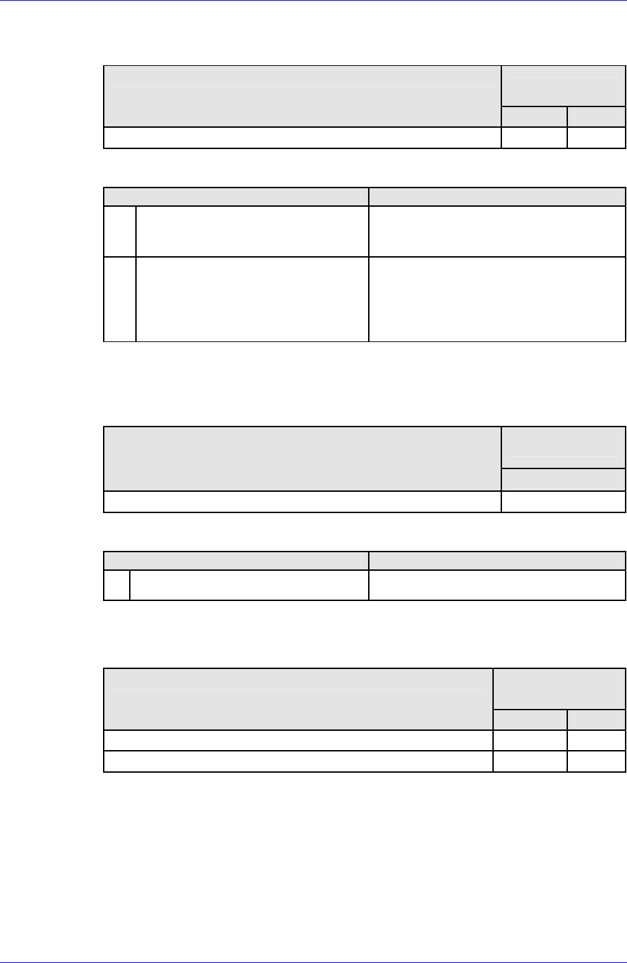
Alarm Code E2H (EEPROM internal data error)
Operating state when alarm occurred
Possible causes
Operating state
1 2
When control power supply is turned on Low High
Corrective measures
Cause Corrective measures
1
CPU is unable to read correct value
from non-volatile memory built-in
the amplifier.
Replace servo amplifier
2
Unable to write to non-volatile
memory at last turning OFF.
After changing some parameters,
confirm no alarm occurrence when
power supply is connected to source
again. →In case that an alarm
continues, replace servo amplifier.
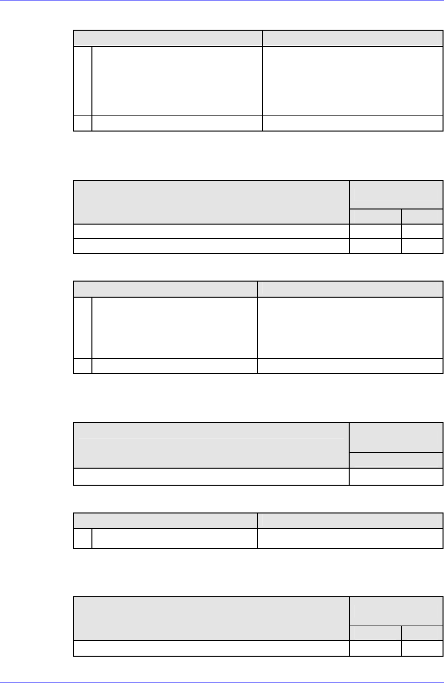
Alarm Code E3H (Internal RAM error)
Alarm Code E4H (Process error between CPU and ASIC)
Operating state when alarm occurred
Possible causes
Operating state
1
When control power supply is turned on High
Corrective measures
Cause Corrective measures
1 Faulty amplifier control board. Replace servo amplifier
Alarm Code E5H (Parameter error 1)
Operating state when alarm occurred
Possible causes
Operating state
1 2
When control power supply is turned on High High
After changing any system parameters High
7-53
Samsung Component Placer CP45FV Series Maintenance Guide
Corrective measures
Cause
Corrective measures
1
The value of system parameter is
outside the setting range.
Check servo amplifier model.
Check the setting value of system
parameter and correct it.
→Turn on the power supply again and
check no alarm.
2 Faulty servo amplifier Replace servo amplifier
Alarm Code E6H (Parameter error 2)
Operating state when alarm occurred
Possible causes
Operating state
1 2
When control power supply is turned on High High
After changing any system parameters High
Corrective measures
Cause Corrective measures
1
The setting value of system
parameter does not match that of
actual hard ware.
Wrong combination of system
parameter setting
Check servo amplifier model.
Check the setting value of system
parameter and correct it. →Turn on
the power supply again and check no
alarm.
2 Faulty servo amplifier Replace servo amplifier
Alarm Code F1H (Task process error)
Operating state when alarm occurred
Possible causes
Operating state
1
During operation High
Corrective measures
Cause Corrective measures
1 Faulty amplifier control circuit Replace servo amplifier.
Alarm Code F2H (Initial timeout)
Operating state when alarm occurred
Possible causes
Operating state
1 2
When control power supply is turned on High High
7-54
Inspection of the Controller
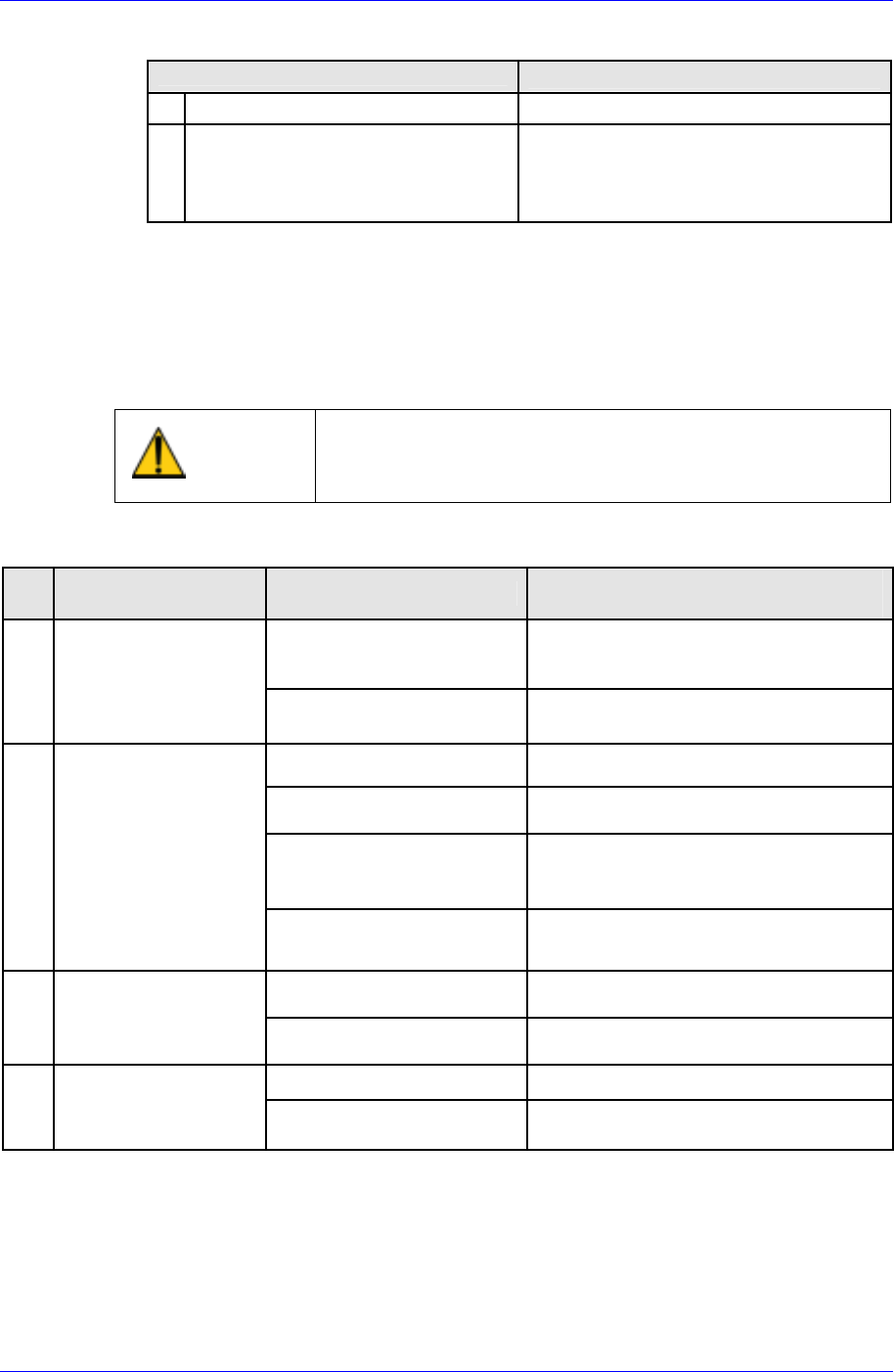
Corrective measures
Cause
Corrective measures
1 Faulty amplifier internal circuit Replace servo amplifier.
2 Malfunction due to noise
Check that amplifier earth cable
should be correctly grounded.
Add ferrite core as a countermeasure
against noise.
7.9.2. Taking Measures in case of Operational Malfunction
On the occasion of operational malfunction without an alarm, the following explains
checking points, inferable causes, and countermeasures. Consult your Sanyo Denki dealer
should the malfunctions persist even after performing these troubleshooting measures.
Caution
Take note that it is dangerous to perform some of these
procedures without first switching off the main power
supply
Table 7-5. Taking Measures in case of operational malfunction
No
Inferable Causes and
countermeasures
Check voltage of control
power input terminals
1
7-segment LED does
not display “≡“ after
main power supply is
switched on
Check if red “CHARGE”
LED is on
Faulty power supply circuit → Replace
servo amplifier
Check if position command
ii ttd
Input position command.
Check if servo lock is on
Check tightening of screw as motor
power line is not connected
Check if current limit is
inputted
Motor does not rotate, since current
limiter is on and motor cannot generate
torque against the load torque.
2 7 segment LED is
displaying a flashing
“8” (servo ON status),
but motor is not
rotating
Check if deviation clear
remains on
Chancel the deviation clear input (CN1-
34 pin)
Check if proportional
control is on
Stop proportional control input
3
Unstable servomotor
rotation. Lower
rotation than
command.
Check if current limiter is
on.
Stop current limiter input.
Check motor power lines One of the power lines is disconnected.
4
Servomotor rotates
momentarily before
stopping.
Check encoder resolution
setting.
Correct the setting and turn on the
power.
Malfunction Checking points
Check power supply if voltage is low
Check wiring and tightening of
screws if there is no voltage
7-55