Maintenance Reference(CP45FV) Eng.pdf - 第70页
在线预览 Maintenance Reference(CP45FV) Eng.pdf PDF 文档。
Noise Inspection of Machine
Chapter 6. Noise Inspection of Machine
6-1
6.1. Noise Solution
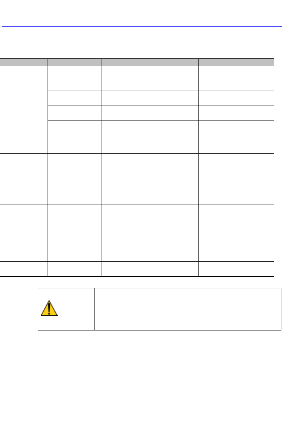
Table 6-1. Noise Solution
Classification Noise Type Possible Cause Sloution
X,Y Axis
noise
.Resonance on
driving motor
.Motor drive failure or abnormal
motor gains.
.Contact Samsung srevice
Center
.Coupling vibration .Coupling bolt is not tightened. .Tighten up the bolt as the
prescribed torque.
.Loud metalic suond
on ball screw
.Metal contact due to insufficient
lubrication.
.Grease the ball screw.
.Irregular meatalic
sound on LM guide
.Small chips or dusts are stuck on
the LM Guide surface.
.Metal contact due to insufficient
lubrication.
.Clean the LM guide suface
.Replenish grease.
Conveyor noise
.PCB driving belt
.Loud metalic noise
on adjusting
conveyor width
.Belt tension is too tight or too
loose.
.Small Chips or dusts are stuck
on the belt or pulley surface.
.Metal contact due to insufficient
lubrication.
.Adjust the belt tension.
.Clean the pulley surface.
.Grease the screws for
adjusting width.
Z Axis
noise
.Loud sound on
driving motor
.Belt tension is too tight.
.Small chips or parts exist
between belt and pulley.
.Adjust the belt tension.
.Remove the interfering
substances in belt or
pulley.
Air pipes
.Air leakage .Air pipes' failure. .Check where the air
leakage occurs and replace
it.
Fan
.Air resistance
noise
.Small Chips or dusts are stuck
on the Fan cover.
.Clean the fan cover hole.
Caution
When a noise problem applying to one of above
classification occurs and if the machine is operated without
correcting the problem, it will affect the life span of the
machine. Be sure to operate the machine after taking proper
corrective actions.
Inspection of the Controller
Chapter 7. Inspection of the Controller
7-1
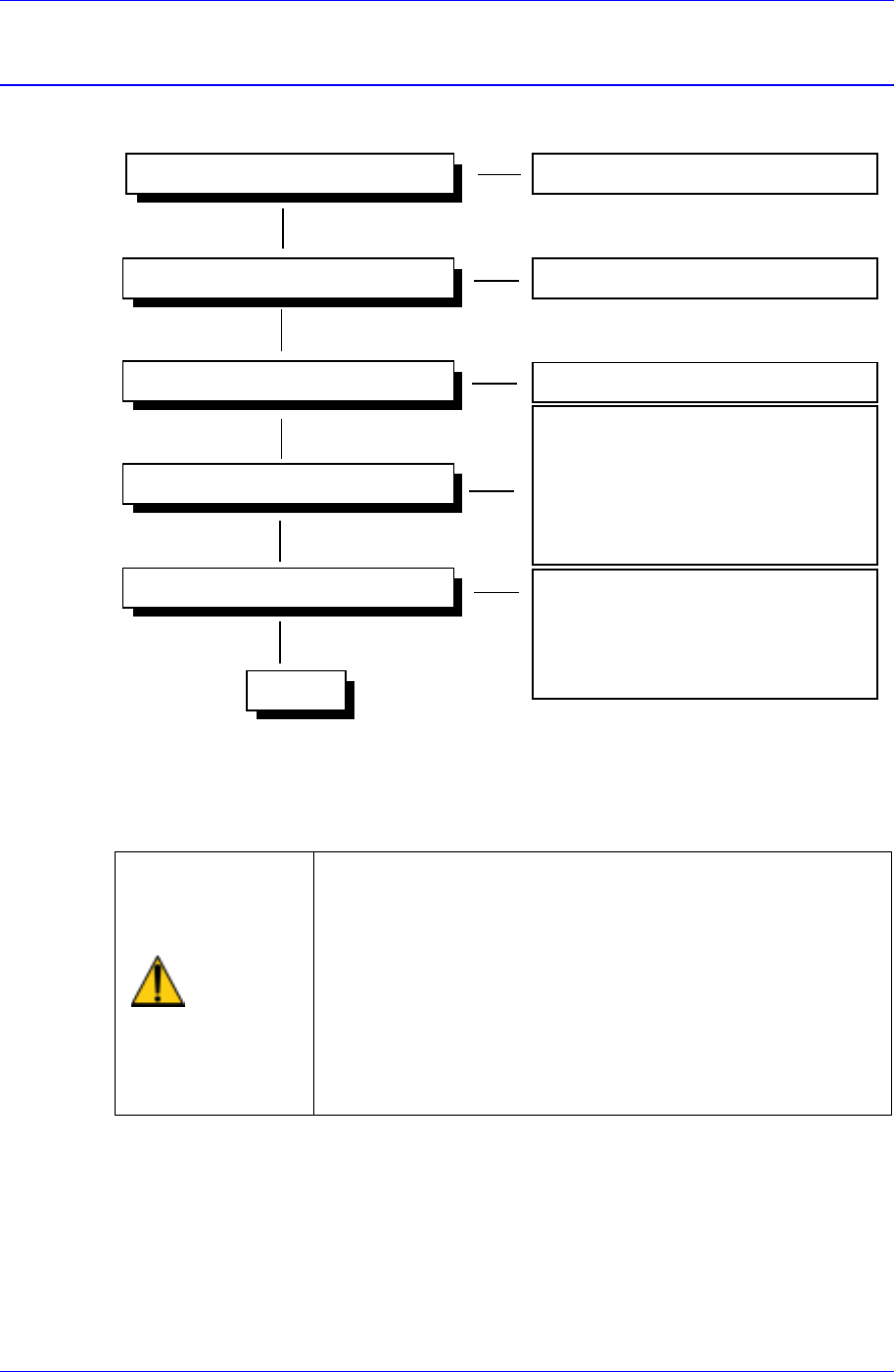
7.1. Power Inspection
Ready Switch
Check the functioning of switch
Isolation Switch
Main Circuit Breaker
Main Start Switch
- Check the EMG Front switch
- Check the EMG Rear switch
- Check the CP1 switch (TURN ON)
- Check the CP2 switch(TURN ON)
- Check the CR1-1,CR1-2,CR3 switches
Operating
- Check the CR3 relay
- Check the CONV I/F CN10
connections.
- Check the CR2-1, CR2-2 switches
Powering On (AC 220V) Check the status of power supply
Check the functioning of switch
CR4
230V
Figure 7-1. Power Inspection
For more details regarding the circuit diagram, refer to the A/S Part List & Drawings
Manual.
Warning
As high voltage current flows in the power supply area of
the Component Placer, if a part of human body or other
conductors touch the equipment, it could result in severe
injuries.
As charged electrons could cause electric shock for a few
minutes after the Component Placer is turned off, the
machine must be handled only by qualified personnel.
And the inspection of the machine must be done while
power supply is turned off and the power plug is
completely disconnected.