Maintenance Reference(CP45FV) Eng.pdf - 第79页
Inspection of the Contr oller 7-9 7.3.1. CAN Master Board Used for the control of data communicati on between the Main CPU Board (MVME162) and each I/O Interface Board of the CP45FV . In addition, it is used for the data…
Samsung Component Placer CP45FV Series Maintenance Guide
NO. PART NO. PART NAME REMARK
1
J4801015A MOTHER BOARD F815D/V FULL-SIZE SBC
2
J4809043A VME CPU BOARD MVME 162PA-252SE
3
J4809047A PCI-6S PCI/ISA BACK PLANE PCI-6S PCI/ISA BACK PLANE
4
J5001008A MODULE RAM SDRAM 128M 168PIN PC133
5
J9060014B CONVEYOR PACK BOARD ASSY 30-CONV3-IO BOARD(2)
6
J9060055A Y SUB BOARD ASS'Y CP-45 REV 1.0
7
J9060059A CAN MASTER BOARD ASS'Y Refer to 7.3.1
8
J9060060C CAN FEEDER BOARD ASS'Y Refer to 7.3.4
9
J9060062B CAN HEAD BOARD ASS'Y Refer to 7.3.2
10
J9060063B CAN CONVEYOR BOARD ASS'Y Refer to 7.3.3
11
J9060132A PC ISA I/F CARD ASS'Y CP-45 REV 1.0
12
J9060139C
CAN STAGE
Illumination
BOARD ASS'Y
Refer to 7.3.5
13
J9060140E
CAN HEAD
Illumination BOARD
ASS'Y
Refer to 7.3.5
14
J9060161A VME AXIS(3) BOARD ASS'Y J9060161A
15
J9060162A VME AXIS(4) BOARD ASS'Y J9060162A
16
J9060229B MK3 AD/DA BOARD ASS'Y MK3 REV 2.1
17
J9060230A MK3 DSP BOARD ASS'Y MK3 REV 2.0
18
J9060231B MK3 MEMORY BOARD ASS'Y MK3 REV 2.1
19
J9800398 X-AXIS I/F BOARD ASS'Y C30-Z2-206-00-20 P/S
20
J4901012A CPU INTEL CELERON 1.3GHz(Including fan)
7-8
Inspection of the Controller
7-9
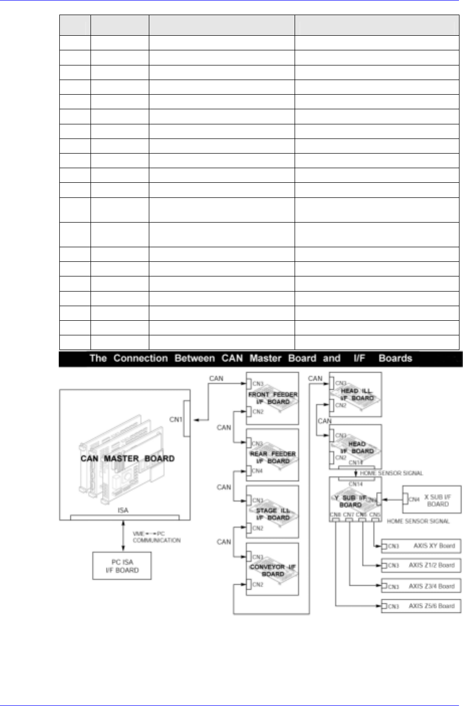
7.3.1. CAN Master Board
Used for the control of data communication between the Main CPU Board (MVME162)
and each I/O Interface Board of the CP45FV. In addition, it is used for the data
communication between the Main CPU Board (MVME162) and the PC for the MMI.
Required power supply
External power input: +12V DC / +5V DC(FROM VME BACKPLANE)
Internal power required: +5V DC
Description of major functions
PART NO. PIN NO. DEF. DESCRIPTION REMARK
1 CANH CAN communication signal
Connection with CAN
communication signal of
other nodes
2 CANL
3 /IO-RES RESET Signal TO CAN SLAVE
CN1/CN3
6 +12V DC+12V for I/O I/F BOARD A/D TO CAN SLAVE
P1/P2 96PIN VME CONN VME BACKPLANE CONNECTOR
J2 100PIN ISA CONN CONNECTOR for PC ISA BUS I/F
U22 100PIN EPM7128
Realization of common RAM interface
logic for VME and PC
U23/U29 28PIN KM68257B
Common RAM for VME⇔PC
U36 80PIN H8S/2134 CPU for CAN MASTER BOARD
U41 44PIN 82527 CAN CONTROLLER
U37 8PIN PCA82C250 CAN BUS DRIVER
U39 52PIN IDT7132
VME⇔H8 DPRAM
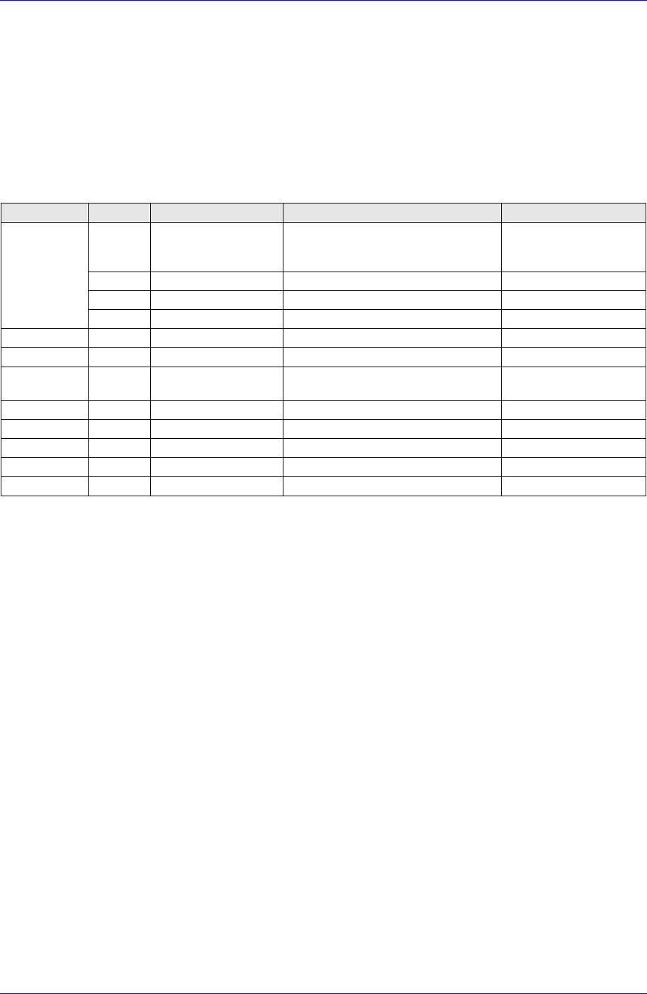
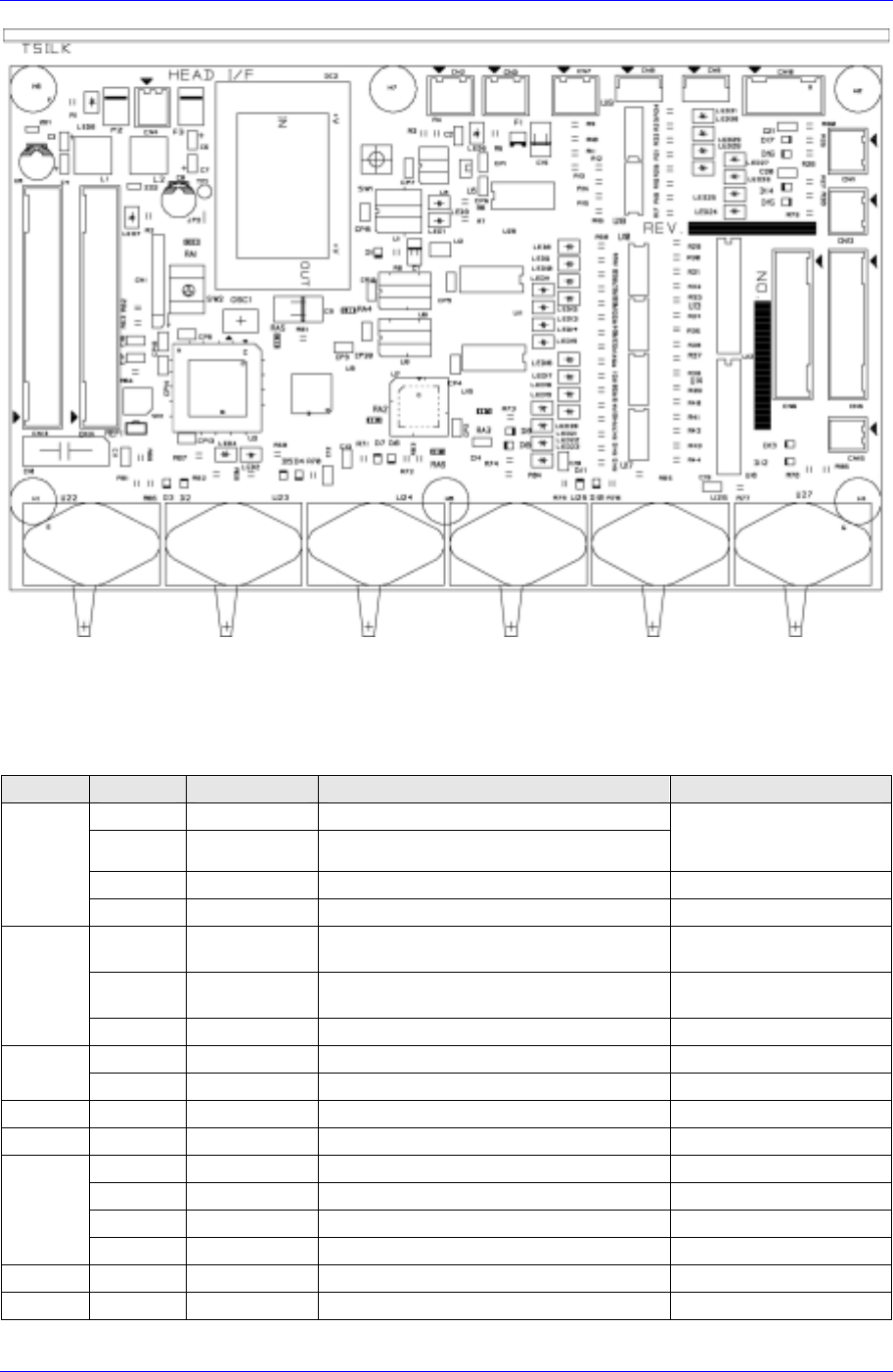
7.3.2. Head Control Board
Receives commands from the CAN Master Board to operate the solenoid valve related to
the head. It also receives the home sensor input signal of the motor related to the head and
transmits it to the CAN Master Board.
Samsung Component Placer CP45FV Series Maintenance Guide
Required power supply
External power input: +24V DC
Internal power required: +5V DC / +24V DC
Description of major functions
PIN NO. DEF. DESCRIPTION REMARK
1 CANH CAN communication signal
2 CANL
Connection with CAN
communication signal of
other nodes
3 /IO-RES RESET Signal FROM CAN MASTER
CN2/CN3
6 +12V +12V for A/D FROM CAN MASTER
1 24VP DC+24V for OUTPUT PORT
Apply after inputting the
READY SW
2 24V DC+24V for INPUT PORT
then DC+5V for BOARD is
generated
CN4
3/4 24G DC+24V GROUND -
2 IN1.0 NOZZLE CHECK SENSOR INPUT 6PIN CONNECTOR
CN7
4 OUT1.7 NOZZLE CHECK SENSOR OFF
CN8 1~3 IN1.2 BAD MARK SENSOR -
CN9 1~3 IN1.3 RESERVED INPUT PORT -
3 IN1.4 RESERVED INPUT PORT -
4 IN1.5 SIDE ILL UP SENSOR -
9 IN1.6 SIDE ILL DOWN SENSOR -
CN10
10 IN1.7 MIRROR SAFETY SENSOR -
U22-27 1 AN0~AN5 VACUUM SENSOR(MPX5100AP) ANALOG INPUT
CN11 3/4 AN6/AN7 RESERVED ANALOG INPUT PORT -
7-10