Maintenance Reference(CP45FV) Eng.pdf - 第88页
Samsung Component Placer CP45FV Series Maintenance Guide 33~48 OUT3.0~3.7 FEEDER SOL #17~#24 49~56 OUT4.0~4.3 FEEDER SOL #25~#28 1~8 OUT4.4~4.7 FEEDER SOL #29~# 32 9~24 OUT5.0~5.7 FEEDER SOL # 33~#40 25~40 OUT6.0~6.7 FEE…
Inspection of the Controller
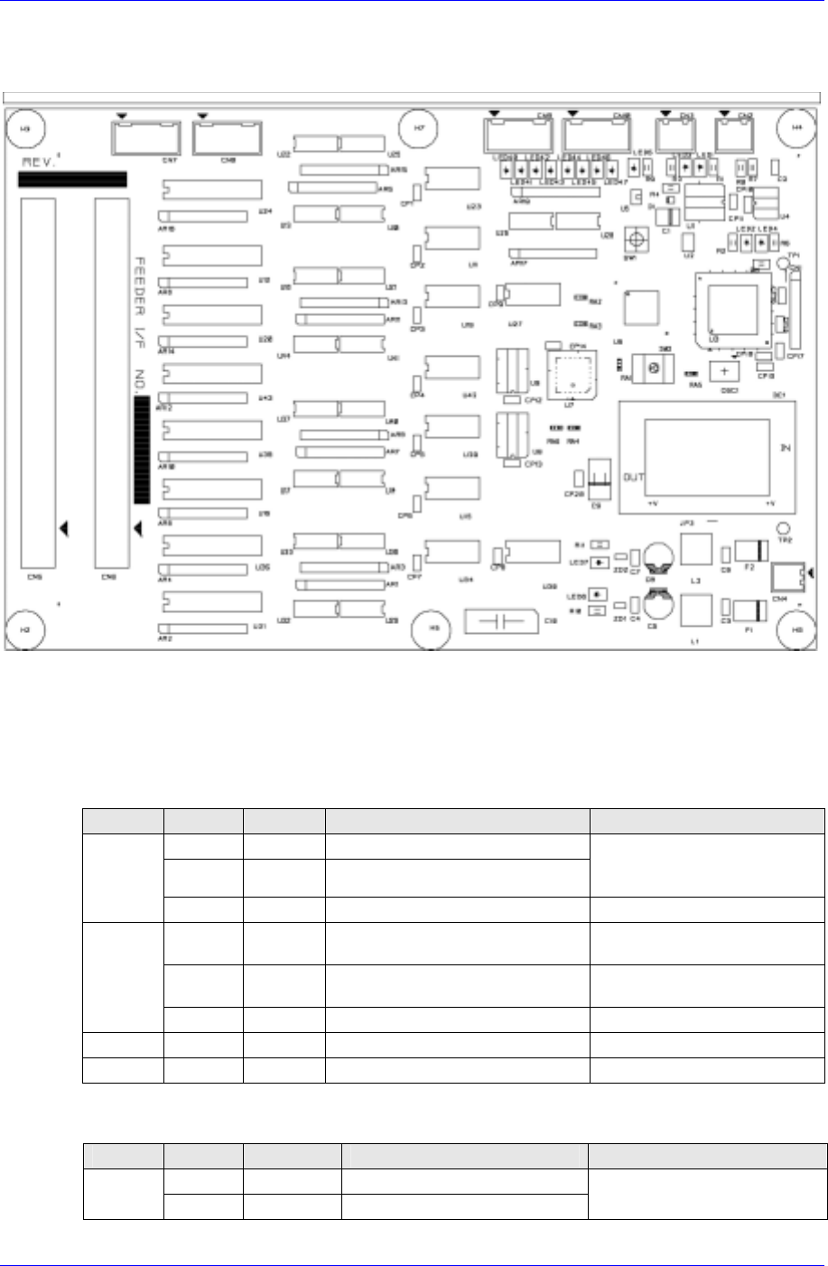
7.3.4. Feeder Control Board
Receives commands from the CAN Master Board to operate the feeder solenoid valve.
Required power supply
External power input: +24V DC
Internal power required: +5V DC / +24V DC
Description of major functions
INPUT
PIN NO. DEF. DESCRIPTION REMARK
1 CANH CAN communication signal
2 CANL
Connection with CAN
communication signal of other
nodes
CN2/CN3
3 /IO-RES RESET Signal FROM CAN MASTER
1 24VP DC+24V for OUTPUT PORT
Apply after inputting the READY
SW
2 24V DC+24V for INPUT PORT
then DC+5V for BOARD is
generated
CN4
3/4 24G DC+24V GROUND -
CN9 1~12 IN1.0~1.3 RESERVED INPUT PORT -
CN10 1~12 IN1.4~1.7 RESERVED INPUT PORT -
OUTPUT
PIN NO. DEF. DESCRIPTION REMARK
1~16 OUT1.0~1.7 FEEDER SOL #1~#8
CN5
17~32 OUT2.0~2.7 FEEDER SOL #9~#16
PIN 57~60 : N.C.
7-17
Samsung Component Placer CP45FV Series Maintenance Guide
33~48 OUT3.0~3.7 FEEDER SOL #17~#24
49~56 OUT4.0~4.3 FEEDER SOL #25~#28
1~8 OUT4.4~4.7 FEEDER SOL #29~#32
9~24 OUT5.0~5.7 FEEDER SOL #33~#40
25~40 OUT6.0~6.7 FEEDER SOL #41~#48
CN6
41~56 OUT7.0~7.7 FEEDER SOL #49~#56
PIN 57~60 : N.C.
FEEDER SOL #53~#56
: NOT USED
CN7 1~12 OUT8.0~8.3 RESERVED OUTPUT PORT -
CN8 1~12 OUT8.4~8.7 RESERVED OUTPUT PORT -
LED information for board status diagnosis
LED ON DESCRIPTION REMARK LED ON DESCRIPTION REMARK
LED1 Can transmission LED5 IO RESET
LED2 Error Occurrence LED6 Board Output Power
LED3 Receiving Can LED7 Board Operation Power
LED4 CPU Operation LED43 Feeder Cart In Input
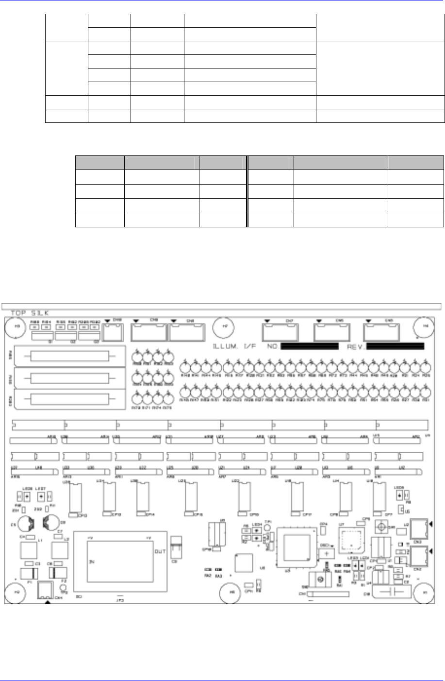
7.3.5. Illumination Control Board – Flying / Stage Camera
Receives commands from the CAN Master Board to adjust the brightness of the lighting
for the flying camera and stage camera. (Head Illumination I/F Board, Stage Illumination
I/F Board)
Required power supply
External power input: +24V DC
Internal power required: +5V DC / +24V DC
7-18
Inspection of the Controller
Description of major functions
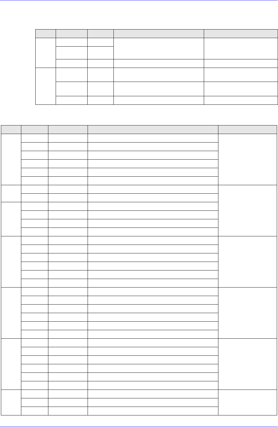
INPUT
PIN NO. DEF. DESCRIPTION REMARK
1 CANH
2 CANL
CAN communication signal
Connection with CAN
communication signal of other
nodes
CN2/
CN3
3 /IO-RES RESET Signal FROM CAN MASTER
1 24VP DC+24V for OUTPUT PORT
Apply after inputting the
READY SW
2 24V DC+24V for INPUT PORT
then DC+5V for BOARD is
generated
CN4
3/4 24G DC+24V GROUND -
OUTPUT
PIN NO. DEF. DESCRIPTION REMARK
1/2 +24VPF Power For LED BOARD
3/4 OUT1.0~1.3
HEAD#1 FRONT(STAGE#1 FRONT)
Illumination
5/6 +24VPF Power For LED BOARD
7/8 OUT1.4~1.7
HEAD#2 FRONT(STAGE#1 UPPER)
Illumination
9/10 +24VPF Power For LED BOARD
CN5
11/12 OUT2.0~2.3
HEAD#3 FRONT(STAGE#1 SIDE)
Illumination
12PIN CONNECTOR
1/2 +24VPF Power For LED BOARD
CN6
3/4 OUT2.4~2.7
HEAD#4 FRONT(STAGE#2 FRONT)
Illumination
5/6 +24VPF Power For LED BOARD
7/8 OUT3.0~3.3
HEAD#5 FRONT(STAGE#2 UPPER)
Illumination
9/10 +24VPF Power For LED BOARD
CN6
11/12 OUT3.4~3.7
HEAD#6 FRONT(STAGE#2 SIDE)
Illumination
12PIN CONNECTOR
1/2 +24VPF Power For LED BOARD
3/4 OUT4.0~4.3
HEAD#1 SIDE(STAGE#3 FRONT)
Illumination
5/6 +24VPF Power For LED BOARD
7/8 OUT4.4~4.7
HEAD#2 SIDE(STAGE#3 UPPER)
Illumination
9/10 +24VPF Power For LED BOARD
CN7
11/12 OUT5.0~5.3
HEAD#3 SIDE(STAGE#3 SIDE)
Illumination
12PIN CONNECTOR
1/2 +24VPF Power For LED BOARD
3/4 OUT5.4~5.7
HEAD#1 DIFFUSE(STAGE#4 FRONT)
Illumination
5/6 +24VPF Power For LED BOARD
7/8 OUT6.0~6.3
HEAD#2 DIFFUSE(STAGE#4 UPPER)
Illumination
9/10 +24VPF Power For LED BOARD
CN8
11/12 OUT6.4~6.7
HEAD#3 DIFFUSE(STAGE#4 SIDE)
Illumination
12PIN CONNECTOR
1/2 +24VPF Power For LED BOARD
3/4 OUT7.0~7.3
HEAD#4 DIFFUSE(STAGE#5 FRONT)
Illumination
5/6 +24VPF Power For LED BOARD
7/8 OUT7.4~7.7
HEAD#5 DIFFUSE(STAGE#5 UPPER)
Illumination
9/10 +24VPF Power For LED BOARD
CN9
11/12 OUT8.0~8.3
HEAD#6 DIFFUSE(STAGE#5 SIDE)
Illumination
12PIN CONNECTOR
1 OUT8.4
BACK
Illumination
3 OUT8.5
BACK
Illumination
CN10
5 OUT8.6
BACK
Illumination
6PIN CONNECTOR
7-19