00198374-01_UG_OSC_Package_DE_EN.pdf - 第55页
4 Working with the OSC Features 4.2 Stereo Measurement for THT Pins Bedienungsanleitung OSC Package User Guide OSC-Paket - 06/2017 55 4.2 Stereo Measurement for THT Pins For correct placement of components with THT pins …
4 Working with the OSC Features
4.1 Placement of Snap-In Components
54 Bedienungsanleitung OSC Package User Guide OSC-Paket - 06/2017
CAUTION
The next board in the input section will be moved in!
If the next board is already present in the input section, it will be moved in and placed
although the first board has not yet been confirmed!
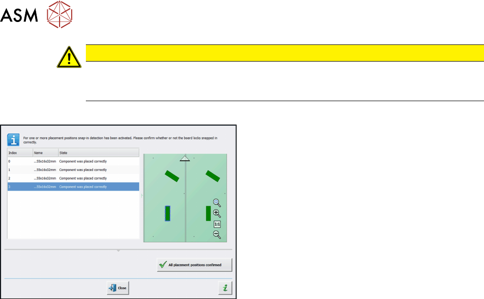
Step 6: Station software
► Check all placement positions at the inspection
station.
► Confirm all placement positions with the All
placement positions confirmed button.
4 Working with the OSC Features
4.2 Stereo Measurement for THT Pins
Bedienungsanleitung OSC Package User Guide OSC-Paket - 06/2017 55
4.2 Stereo Measurement for THT Pins
For correct placement of components with THT pins (Through Hole Technology) it is important to
detect and measure the position of the tip of each pin to fit the pins into the holes on the board.
Since the pins often have different shapes and lengths, it is very difficult or impossible to accurately
locate the center of each tip with conventional 2D measurements. In addition, reflections and other
structures of the component could interfere with the image of the tip and restrain the camera from
determining the THT pin position exactly during a 2D measurement.
Therefore, the new Stereo Measurement for THT pins process has been introduced to measure
THT pins exactly and robustly. The stereo measurement can be used for all components with the
THT round pin and THT square pin pin types. Mixed usage of THT pins and other connection
types, e.g. Gullwing, is currently not possible.
When using the stereo measurement, at least two images are captured per component. Between
capturing the two images the component is moved in x-direction to obtain images of the component
from two different perspectives. Out of the two images a height image is calculated and a 3D image
created showing the component structures very detailed. Depending on the distance to the camera,
an object pixel is displayed at different points on the x-axis in the stereo images. Based on the pos-
ition of an object pixel in the respective stereo image, its distance to the camera can then be calcu-
lated. If necessary, the traverse path can be changed.
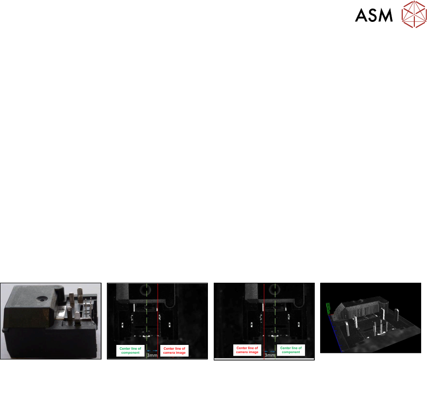
Example
Original component Left image capture Right image capture 3D image as result of
the two measurements
Prerequisites
●
The measurability of the features depends on feature size, feature appearance and back-
ground interference.
●
Currently, only THT round pins and THT square pins are allowed for stereo measurement.
●
Stationary camera types 25 or 33 are required.
●
Minimum features size 145 µ = 9 Pixel:
Camera type 25 = 145 µ
Camera type 33 = 360 µ
●
Minimum feature height: minimum distance between pin top and background:
Camera type 25: 1.0 mm
Camera type 33: 2.0 mm
Recommendation: lead height >= (3 * <height resolution>)
The height resolution depends on the traverse path between the left and right images. For the
default traverse path, the following (pixel) height resolutions are valid:
Camera type 25: 0.49 mm
Camera type 33: 0.9 mm
●
Maximum component size: the rules for the normal 2D measurement minus the traverse path
are applied. The result for the default traverse path
(8 mm for camera type 25, 18 mm for camera type 33) is:
Camera type 25: maximum 55 mm – 8 mm = 47 mm edge length
Camera type 33: maximum 85 mm – 18 mm = 67 mm edge length (or (200 mm – 18 mm) x
(125 mm – 18 mm) = 182 mm x 107 mm with restrictions)
These values refer to the multiple measurement.
●
Supported placement heads:
Twin Head (all high force variants included)
CPP (in Pick&Place mode, if equipped with stationary camera)

4 Working with the OSC Features
4.2 Stereo Measurement for THT Pins
56 Bedienungsanleitung OSC Package User Guide OSC-Paket - 06/2017
4.2.1 Procedure
The following overview lists the single work steps that have to be performed in the specified order
to perform the stereo measurement when THT components are placed.
Performing Stereo Measurement
Step Action SIPLACE program
1) Enabling OSC package SIPLACE Pro
2) Setting component height (overall height or creep distance) –
Observing focus height
SIPLACE Pro
3) If a nozzle gripper is used, setting the nozzle height SIPLACE Pro
4) Enabling stereo measurement for THT pins SIPLACE Vision
5) If necessary, changing the traverse path in the stereo height
view
SIPLACE Vision