semi合集-English.pdf - 第1053页
SEMI E4-0699 © SE MI 1980, 1999 15 R1-2 Isolation R1-2.1 As mentio ned in Section 3.4 , the standard RS- 232-C line does not prov ide isolation betw een the groun ds of remote equipment an d a central computer. It is oft…
SEMI E4-0699 © SEMI 1980, 1999 14
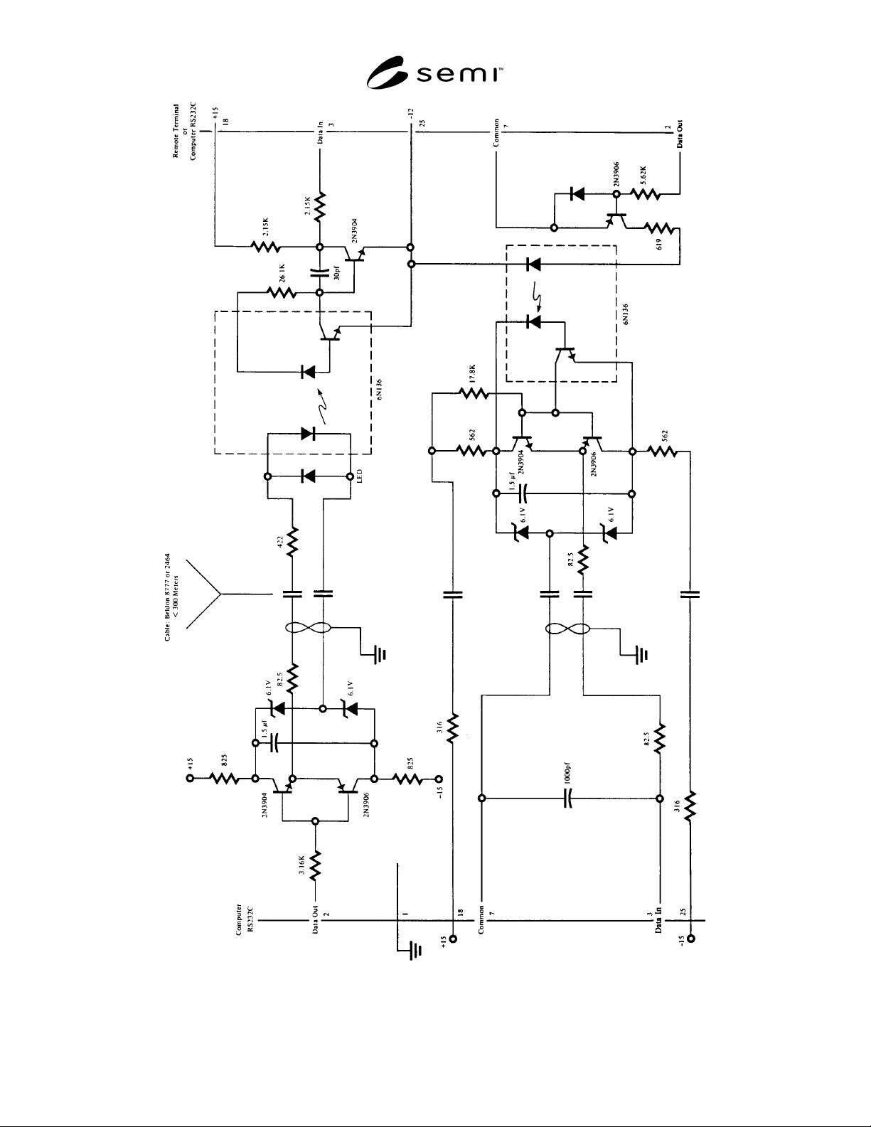
Figure R1-1
RS-232 Isolation Example
SEMI E4-0699 © SEMI 1980, 199915
R1-2 Isolation
R1-2.1 As mentioned in Section 3.4, the standard RS-
232-C line does not provide isolation between the
grounds of remote equipment and a central computer. It
is often desirable to provide isolation to minimize
communications errors and to protect equipment. The
following example is provided here to illustrate how
such an isolation might be provided between two
devices using RS-232-C, while at the same time
providing the capability to drive longer lines. This
description is provided for information only and is not
part of the standard.
R1-2.2 Figure R1-1 illustrates a possible circuit for
isolation which provides line isolation and line driving
capability. The two wires used to provide power to the
remote isolator are required since any local power
supply would have the same isolation problems as the
data wires. The power wires also eliminate extra
supplies at every terminal or remote device. There are
many other possible circuits. This example has been
used successfully and works quite well at 9600 baud for
lines less than 300 meters and illustrates the use of the
voltages on pins 18 and 25 as mentioned in 3.2.4.
R1-3 Examples of Block Transfer Protocol
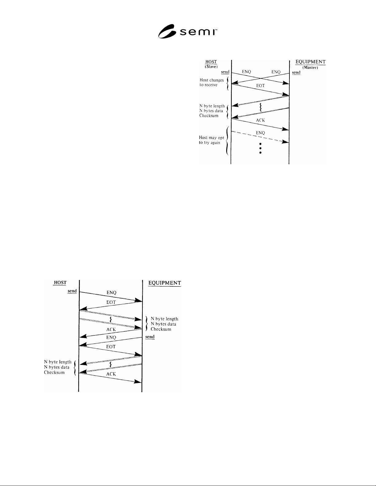
R1-3.1 Figures R1-2 and R1-3 illustrate some simple
message interactions between the host and the
equipment. Figure R1-2 shows the handshake sequence
possible to acquire the status of the equipment. Fig-ure
R1-3 shows the sequence of events when both the host
and the equipment try to send at the same time.
Figure R1-2
Ask for Status
Figure R1-3
Contention Resolution
R1-4 Use of Buffers in the Block Transfer
Protocol
R1-4.1 In the flow chart of the Block Transfer Protocol
(Figure 2), the flow chart entry "LISTEN" implies that
characters are recognized after entering the given state
and not before. If the particular implementation uses
buffers and stores all of the characters received before
the "LISTEN" state is achieved, care must be taken in
the proper handling of the data in the buffer to avoid
problems due to "timing windows" between sending
and receiving.
R1-4.2 If the buffer is cleared before sending the last
character prior to the "LISTEN" (last checksum byte in
sending a message, ENQ or EOT in line control), there
is still a time, albeit small, where spurious characters
could be received into the buffer.
R1-4.2.1 In addition, during the sending of the
message, a delay between the checksum bytes while the
buffer is cleared may cause an inter-character timeout
by the receiver. If the buffer is cleared after the last
character sent before the "LISTEN," there is a
possibility that the desired character will be cleared
from the buffer.
R1-4.3 One solution is to look at the buffer after
entering the "LISTEN" state and examine the last
character in the buffer, if any are there. This works
while listening for an EOT after sending an ENQ. In the
case where the sender is listening for an ACK after
sending the second checksum byte, it is possible that
the receiver also has a block to send, and follows the
SEMI E4-0699 © SEMI 1980, 1999 16
ACK immediately with an ENQ. In this case the last
character in the buffer might be an ENQ, and so the last
two characters should be examined. If an ACK
precedes the ENQ, then it should be assumed that the
block was sent successfully, and the ENQ should be
saved for establishing line control (i.e., send an EOT, or
an ENQ if there is contention).
R1-4.4 The handling of the buffer when listening for
the length byte is not improved by this suggestion. The
buffer should be cleared after the ENQ is received and
before the EOT is sent. Spurious characters received
before the length byte will cause a send failure.
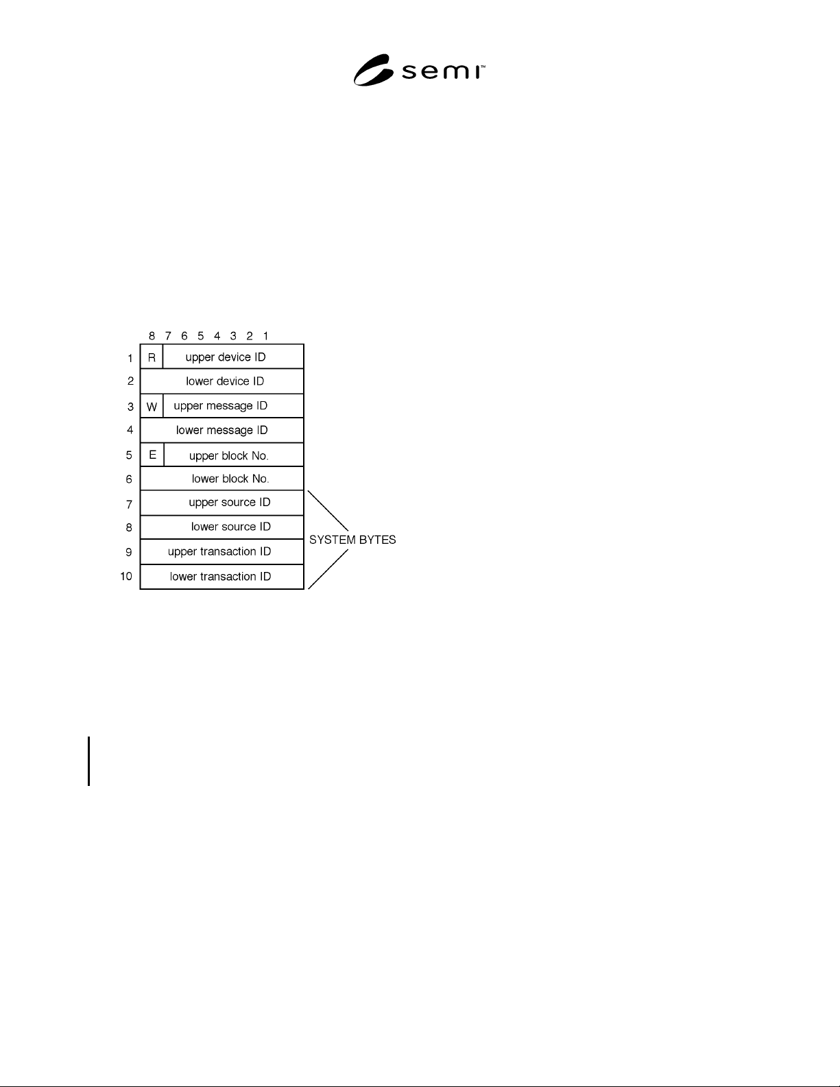
Figure R1-4
Possible Bock Header Structure
R1-5 System Bytes
R1-5.1 This section presents a sample scheme for
generating and managing the system bytes field of the
block header. There are many possible implementations
which meet the requirements of SECS-I. This section
describes one of those implementations.
R1-5.2 Source ID and Transaction ID — The system
bytes are divided into two parts, a source ID and a
transaction ID, as shown in Figure R1-4.
R1-5.3 Distinct source IDs are assigned to each
application level originator of primary messages in a
host or equipment. This allows a secondary message to
be routed to the source of the corresponding primary
message of the transaction. The transaction ID is an
integer that is incremented for each primary message
sent by the SECS-I interface. It is the same for all
blocks of a multi-block message.
R1-5.4 Actions — When a SECS-II message is passed
to the SECS-I protocol, the least significant bit of the
lower message ID is examined to determine whether the
message is primary (bit 1 = 1) or secondary (bit 1 = 0)
message. If the message is primary, transaction ID is
generated and placed in the transaction ID portion of
the system bytes. One method for generating the
transaction ID is to start with a value of 0 upon
initialization, and increment by 1 for each new
transaction, starting with 1 (not 0) when the largest
transaction ID value has been used. At the same time,
the application sender's source ID is placed in the
source ID portion of the system bytes. If the message is
secondary, the system bytes are the same as those of the
corresponding primary message. It is assumed that the
application generating the reply can identify the reply to
the message protocol, which has saved the system bytes
from the primary message.
R1-5.5 Block Send Failures (see Sections 5.8.2 and
6.8.1) — Since it is a requirement that the system bytes
be distinct from those used in blocks that were not
successfully sent since the last successful block send,
the use of two bytes for the transaction ID would
effectively satisfy the requirement by allowing for up to
65,536 consecutive block send failures.
R1-6 Using SECS in a Network
R1-6.1 The SECS standard can be used to control the
flow of data within a network of computers. A network
is an interconnection of computers or intelligent
controllers communicating with one another over
communications lines. Each intelligent entity is a node
of the network. Each node may have a number of
connections to other members of the network.
R1-6.2 One connection of equipment and computers is
in the form of a tree network with the processing
equipment at the ends of branches as shown in Figure
R1-5. Intermediate Nodes A and B service like pieces
of equipment; i.e., all the furnaces to Node A, all
masking to Node B, and so on, for more nodes.
R1-6.3 Node A monitors the three stations 1A, 2A, and
3A. Node A handles most of the normal requirements
of coordinating 1A, 2A, and 3A. Node A receives
instructions from Node C regarding the behavior
desired from 1A, 2A, and 3A. A CRT or operator
interface connected to Node A is shared by 1A, 2A, and
3A. Any node can direct messages up or down the tree.
A message such as an alarm can be sent from 1A to
Node A and from Node A to Node C which might be
considered the host of the network. Node A might be
part of a system supplied by a company which has its
own communications scheme for devices tied to Node
A. As long as the company provides one connection to
Node A which is consistent with this standard, then