semi合集-English.pdf - 第1056页
SEMI E4-0699 © SE MI 1980, 1999 18 be assum ed that an error h as occurred and the receiving machine sh o uld release any memory it may be holding for the transaction. If memory were to remain allocated to incom plete tr…
SEMI E4-0699 © SEMI 1980, 199917
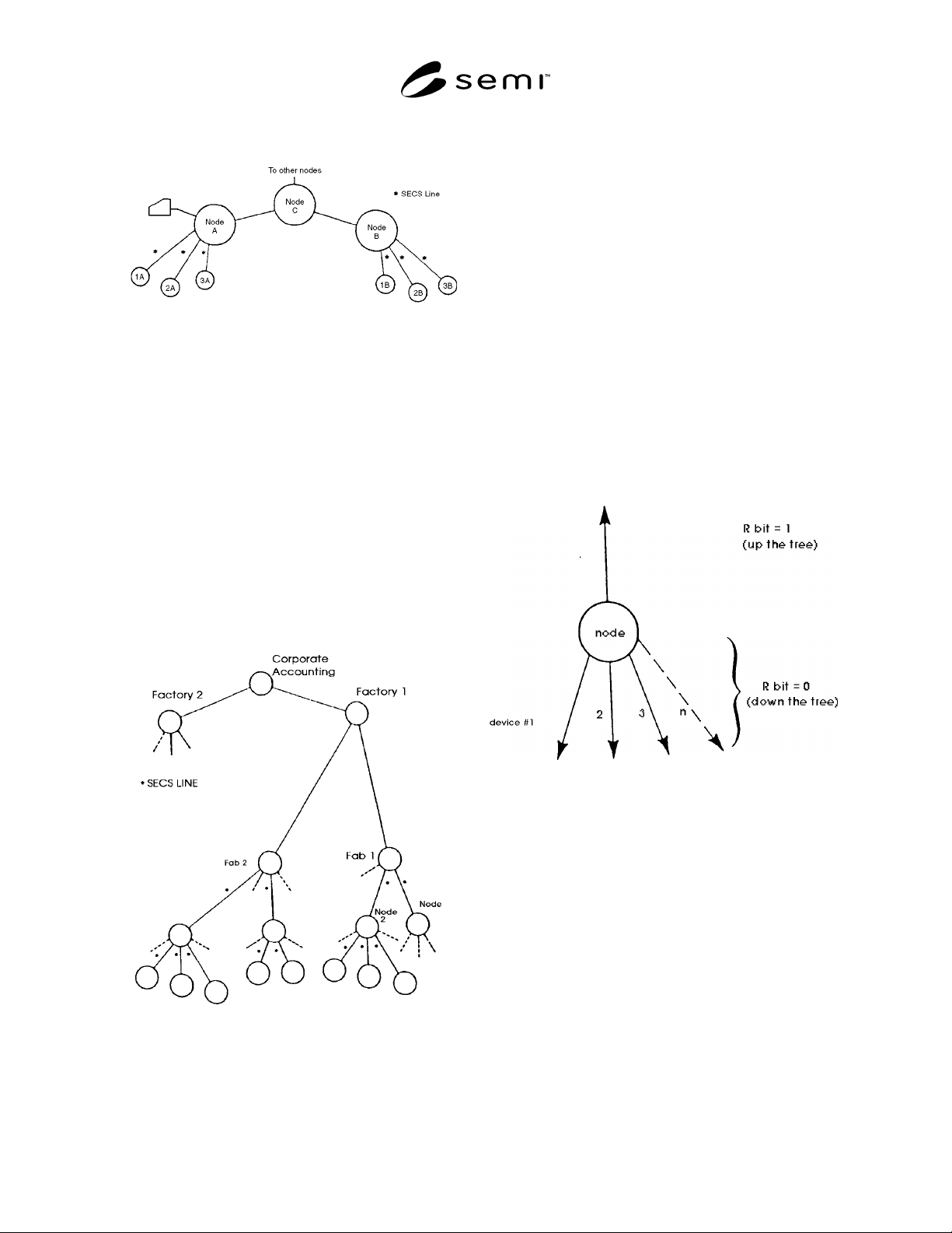
Node A and its attached equipment can be connected to
the host, Node C, and collectively be called one node.
Figure R1-5
Tree Network
R1-6.4 This tree structure can be extended even further
as shown in Figure R1-6 to include multiple
manufacturing plants at remote sites. However, the
primary intent of this standard is to address the
communication between processing equipment and a
host. At higher levels of the tree, the message is
combined with more system level messages and more
computer file manipulations. At these levels, the
communications may require more complex or higher
speed standards. Thus, the SECS line is intended to be
used within one integrated circuit manufacturing area
rather that between general purpose computer centers,
although its only limitations for such a use would be
speed.
Figure R1-6
Extended Tree Network for a Large Organization
R1-6.5 The tree network is characterized by the fact
that there is only one possible path between any two
nodes in the network. This feature makes handling
messages in the tree network relatively easy when
compared to networks where more than one
communication path exists between nodes. In these
latter networks, the nodes must make some judgment
about which path to take, perhaps based on the
conditions of the lines or on the destination of the
message.
R1-6.6 The device ID and the R (Reply) bit play an
important role in directing messages in the network.
Each node of the three maintains a table of the device
below it. From the device code, it knows on which
branch to send the data. When a message is going from
the central node toward the device, the R-bit is set to 0.
When a message is being sent from the device up the
tree, the R-bit is set to 1. When a node sees the R-bit set
to 1, the message must take the one communication
direction that goes up the tree structure. Thus, the R-bit
serves to direct messages up the tree or down the tree,
depending on its value. At any given node, this
behavior may be explained in Figure R1-7.
Figure R1-7
Message Handling at a Node by Using the R-Bit
R1-7 The General Node Transaction Protocol
R1-7.1 The transaction protocol has three primary
functions. First, it coordinates the receiving of
messages that arrive in multiple blocks. Second, it
provides a mechanism for matching primary and
secondary messages. Third, it does error detection on
incomplete messages whether they are due to a break
during multiple blocks or a lack of reply messages. The
third function is vital to the maintenance of a working
system, as can be seen from the following discussion.
Once a transaction is begun with the first block of a
primary message, the receiving machine will have some
memory allocated to buffering or pointing to
interpreting modules. If the transaction remains
incomplete for some reasonable length of time, it may

SEMI E4-0699 © SEMI 1980, 1999 18
be assumed that an error has occurred and the receiving
machine should release any memory it may be holding
for the transaction. If memory were to remain allocated
to incomplete transactions, conceivably the receiving
machine could run out of available memory and would
be unable to function properly. For this reason, the error
detection of incomplete transactions is an essential part
of the message transaction protocol in SECS-I.
R1-7.2 The message transaction protocol is based on a
system of timers called transaction timers. These timers
are maintained in software and are associated with a
given transaction. Once a transaction is begun, there
will exist a timer on the time interval between all blocks
of the transaction independent of the direction of the
message. The machine that expects to receive a block
has the burden of timing and error detection. Timers are
required in any machine that (1) makes a request and
expects to receive data back; (2) must receive multiple
block requests; or (3) sends data and expects an
acknowledgement. A machine may require several
transaction timers if it can conduct multiple transactions
at one time on one port or has multiple ports. A
message timer will exist for each link involved in the
transaction. This allows the error detection to identify
the particular link which has failed.
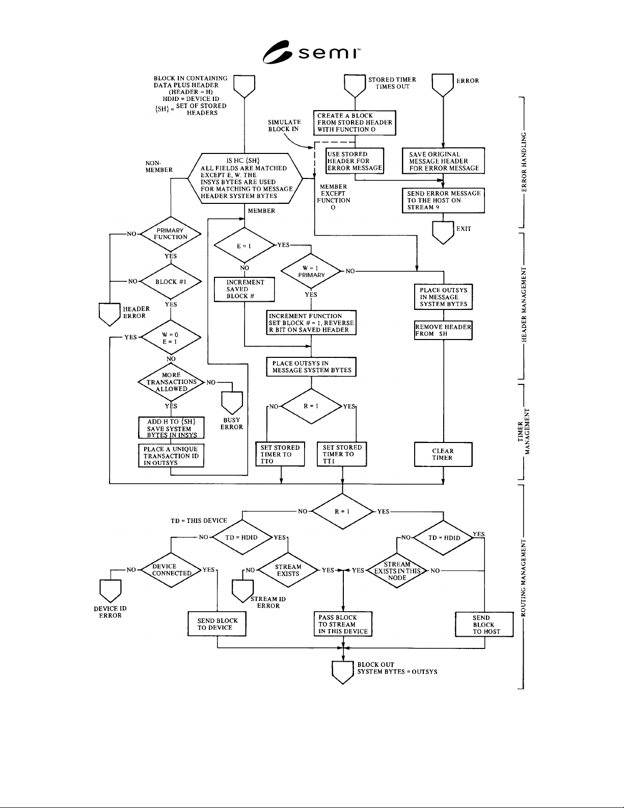
R1-7.3 A general algorithm can be constructed to
handle an arbitrary number of SECS ports. Such an
algorithm is presented in the form of a flow chart in
Figure R1-8. There is one such algorithm for each
device ID. The algorithm handles all SECS data blocks
that enter, leave or pass the device ID. A new block
causes the procedure to be executed starting from the
point marked "block in" and continues until the point
marked "block out." The block of data will then be
directed to the proper destination.
R1-7.4 This algorithm makes use of a stored version of
the message header for each transaction being handled.
The stored header may be visualized as shown in Figure
R1-9. The stored header has two system areas and an
associated transaction timer. The two system areas are
required to keep the incoming and the outgoing system
areas independent in coding, yet related in meaning.
The two system areas are referred to by the state of the
R-bit in the message block header. One area is related
to R = 0 and the other R = l. When a prime message is
received that requires a reply, the system bytes from the
block are stored in the system area corresponding to the
opposite state of the R bit on the message. When the
reply is sent, the system bytes are used from the store
system bytes corresponding to the same R-bit as the
reply. The system area corresponding to the same R-bit
as the message is called OUTSYS while the system
area corresponding to the opposite R-bit is called
INSYS.
R1-7.5 When a block is presented to this algorithm, the
first task is to determine if the block is part of an
ongoing transaction, the first block of a new
transaction, or some other unknown block. This test is
accomplished by comparing the header of the block
with the stored headers. If a match is not found, then a
check is made to see if the block is the first of a primary
message. If this is true, then a new header is added to
the stored header list. If the primary message is only
one block long and requires no reply, then no stored
header is created. When a match is found, the algorithm
modifies the stored header so that it will look like the
next block of the transaction to be expected. On all
blocks requiring a stored header, except the last, a
transaction timer is set to a timeout value prior to
sending the block to its destination. The last part of the
algorithm directs the block to its destination or detects
an error in the destination.
R1-7.6 Error recovery is an important part of the
algorithm to ensure that the system will remain
operational in spite of bad data blocks. For any block
that does not pass the tests described in the algorithm,
the header of the message is saved and sent in the host
direction on a Stream 9 error message. This information
can be useful in tracking down the source of the error.
Another type of error occurs when one of the
transaction timers times out. Such an error message
means that the transaction has been interrupted. An
error message is formed which sends the stored header
in the host direction on Stream 9. The stored header and
the timer are then released. This procedure aids in
keeping software cleared and ready in case of
difficulties in the network.
SEMI E4-0699 © SEMI 1980, 199919
Figure R1-8
General Node Transaction Algorithm