semi合集-English.pdf - 第1332页
SEMI E30-1103 © SEMI 1992, 2003 6 SEMI E37) for a protocol-specific definition of comm unication failure. 2.5 communication fault — A com munication fault occurs when the equipment does not receive an expected message, o…

SEMI E30-1103 © SEMI 1992, 2003
5
Section 7 — SECS Message Subset
This section provides a composite list of the SECS-II
messages required to implement all capabilities defined
in the GEM standard.
Section 8 — GEM Compliance
This section describes the fundamental GEM
requirements and additional GEM capabilities and
provides references to other sections of the standard
where detailed requirements are located. This section
also defines standard terminology and documentation
that can be used by equipment suppliers and device
manufacturers to describe compliance with this
standard.
Section A — Application Notes
These sections provide additional explanatory
information and examples.
Section A.1 — Factory Operational Script
This section provides an overview of how the required
SECS capabilities may be used in the context of a
typical factory operation sequence. This section is
organized according to the sequence in which actions
are typically performed.
Section A.2 — Equipment Front Panel
This section provides guidance in implementing the
required front panel buttons, indicators, and switches as
defined in this document. A summary of the front panel
requirements is provided.
Section A.3 — Examples of Equipment Alarms
This section provides examples of alarms related to
various equipment configurations.
Section A.4 — Trace Data Collection Example
This section provides an example of trace initialization
by the host and the periodic trace data messages that
might be sent by the equipment.
Section A.5 — Harel Notation
This section explains David Harel’s “Statechart”
notation that is used throughout this document to depict
state models.
Section A.6 — Example Control Model Application
This section provides one example of a host’s
interaction with an equipment’s control model.
Section A.7 — Examples of Limits Monitoring
This section contains four limits monitoring examples
to help clarify the use of limits and to illustrate typical
applications.
1.5 Applicable Documents
1.5.1 SEMI Standards — The following SEMI
standards are related to the GEM standard. The specific
portions of these standards referenced by GEM
constitute provisions of the GEM standard.
SEMI E4 — SEMI Equipment Communications
Standard 1 — Message Transfer (SECS-I)
SEMI E5 — SEMI Equipment Communications
Standard 2 — Message Content (SECS-II)
SEMI E13 — Standard for SEMI Equipment
Communication Standard Message Service (SMS)
SEMI E23 — Specification for Cassette Transfer
Parallel I/O Interface
1.5.2 Other References
Harel, D., “Statecharts: A Visual Formalism for
Complex Systems,” Science of Computer Programming
8 (1987) 231-274
1
.
NOTICE: As listed or revised, all documents cited
shall be the latest publications of adopted standards.
2 Definitions
2.1 alarm — An alarm is related to any abnormal
situation on the equipment that may endanger people,
equipment, or material being processed. Such abnormal
situations are defined by the equipment manufacturer
based on physical safety limitations. Equipment
activities potentially impacted by the presence of an
alarm shall be inhibited.
2.1.1 Note that exceeding control limits associated
with process tolerance does not constitute an alarm nor
do normal equipment events such as the start or
completion of processing.
2.2 capabilities — Capabilities are operations
performed by semiconductor manufacturing equipment.
These operations are initiated through the
communications interface using sequences of SECS-II
messages (or scenarios). An example of a capability is
the setting and clearing of alarms.
2.3 collection event — A collection event is an event
(or grouping of related events) on the equipment that is
considered to be significant to the host.
2.4 communication failure — A communication failure
is said to occur when an established communications
link is broken. Such failures are protocol specific. Refer
to the appropriate protocol standard (e.g., SEMI E4 or
1 Elsevier Science, P.O. Box 945, New York, NY 10159-0945,
http://www.elvesier.nl/homepage/browse.htt

SEMI E30-1103 © SEMI 1992, 2003
6
SEMI E37) for a protocol-specific definition of
communication failure.
2.5 communication fault — A communication fault
occurs when the equipment does not receive an
expected message, or when either a transaction timer or
a conversation timer expires.
2.6 control — To control is to exercise directing
influence.
2.7 equipment model — An equipment model is a
definition based on capabilities, scenarios, and SECS-II
messages that manufacturing equipment should perform
to support an automated manufacturing environment.
(See also Generic Equipment Model.)
2.8 event — An event is a detectable occurrence
significant to the equipment.
2.9 GEM compliance — The term “GEM Compliance”
is defined with respect to individual GEM capabilities
to indicate adherence to the GEM standard for a
specific capability. Section 8 includes more detail on
GEM Compliance.
2.10 Generic Equipment Model — The Generic
Equipment Model is used as a reference model for any
type of equipment. It contains functionality that can
apply to most equipment, but does not address unique
requirements of specific equipment.
2.11 host — The SEMI E4 and E5 standards define
Host as “the intelligent system that communicates with
the equipment.”
2.12 message fault — A message fault occurs when the
equipment receives a message that it cannot process
because of a defect in the message.
2.13 operational script — An operational script is a
collection of scenarios arranged in a sequence typical of
actual factory operations. Example sequences are
system initialization powerup, machine setup, and
processing.
2.14 operator — A human who operates the equipment
to perform its intended function (e.g., processing). The
operator typically interacts with the equipment via the
equipment supplied operator console.
2.15 process unit — A process unit refers to the
material that is typically processed as a unit via single
run command, process program, etc. Common process
units are wafers, cassettes, magazines, and boats.
2.16 processing cycle — A processing cycle is a
sequence wherein all of the material contained in a
typical process unit is processed. This is often used as a
measure of action or time.
2.17 scenario — A scenario is a group of SECS-II
messages arranged in a sequence to perform a
capability. Other information may also be included in a
scenario for clarity.
2.18 SECS-I — SEMI Equipment Communications
Standard 1 (SEMI E4). This standard specifies a
method for a message transfer protocol with electrical
signal levels based upon EIA RS232-C.
2.19 SECS-II — SEMI Equipment Communications
Standard 2 (SEMI E5). This standard specifies a group
of messages and the respective syntax and semantics
for those messages relating to semiconductor
manufacturing equipment control.
2.20 SMS — SECS Message Service. An alternative to
SECS-I to be used when sending SECS-II formatted
messages over a network.
2.21 state model — A State Model is a collection of
states and state transitions that combine to describe the
behavior of a system. This model includes definition of
the conditions that delineate a state, the
actions/reactions possible within a state, the events that
trigger transitions to other states, and the process of
transitioning between states.
2.22 system default — Refers to state(s) in the
equipment behavioral model that are expected to be
active at the end of system initialization. It also refers to
the value(s) that specified equipment variables are
expected to contain at the end of system initialization.
2.23 system initialization — The process that an
equipment performs at power-up, system activation,
and/or system reset. This process is expected to prepare
the equipment to operate properly and according to the
equipment behavioral models.
2.24 user — A human or humans who represent the
factory and enforce the factory operation model. A user
is considered to be responsible for many setup and
configuration activities that cause the equipment to best
conform to factory operations practices.
3 State Models
The following sections contain state models for
semiconductor manufacturing equipment. These state
models describe the behavior of the equipment from a
host perspective in a compact and easy to understand
format. State models for different equipment will be
identical in some areas (e.g., communications), but may
vary in other areas (e.g., processing). It is desirable to
divide the equipment into parallel components that can
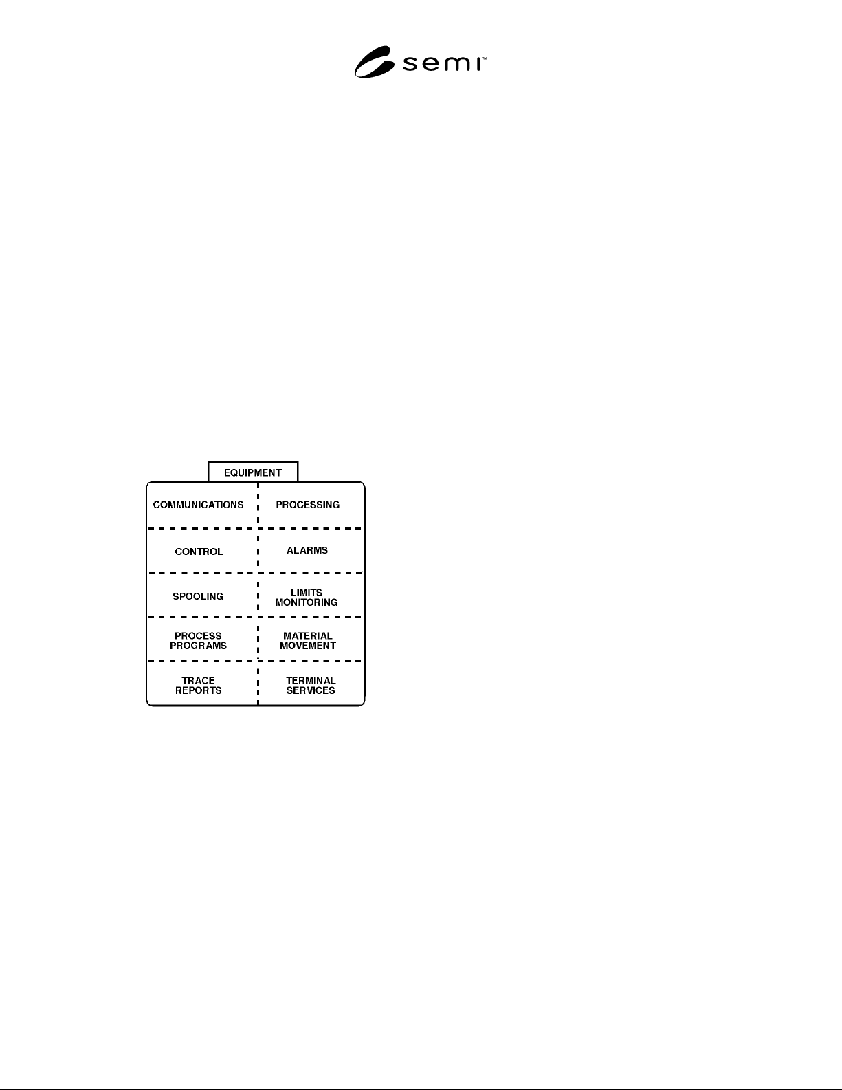
be modeled separately and then combined. An example
of a component overview of an equipment is provided
as Figure 3.0.
SEMI E30-1103 © SEMI 1992, 2003
7
Equipment manufacturers must document the
operation-al behavior of their equipment using state
model meth-odology. State models are discussed in
Sections 3.1 and A.5 and in a referenced article.
Documentation of a state model shall include the
following three elements:
— A state diagram showing the possible states of the
system or components of a system and all of the
possible transitions from one state to another. The
states and transitions must each be labeled. Use of
the Harel notation (see A.5) is recommended.
— A transition table listing each transition, the
beginning and end states, what stimulus triggers
the transition, and any actions taken as a result of
the transition.
— A definition of each state specifying system
behavior when that state is active.
Examples of the above elements are provided in
Section A.5.
Figure 3.0
Example Equipment Component Overview
The benefits of providing state models are:
1. State machine models are a useful specification
tool,
2. A host system can anticipate machine behavior
based upon the state model,
3. End-users and equipment programmers have a
common description of machine behavior from
which to work,
4. “Legal” operations can be defined pertaining to
any machine state,
5. External event notifications can be related to
internal state transitions,
6. External commands can be related to state
transitions,
7. State model components describing different
aspects of machine control can be related to one
another (example: processing state model with
material transport state model; processing state
model with internal machine safety systems).
3.1 State Model Methodology — To document the
expected functionality of the various capabilities
described in this document, the “Statechart” notation
developed by David Harel has been adopted. An article
by Harel is listed in Section 1.5 and should be
considered “must” reading for a full understanding of
the notation. The convention used in this and following
sections is to describe the dynamic functionality of a
capability with three items: a textual description of each
state or substate defined, a table that describes the
possible transitions from one state to another, and a
graphical figure that uses the symbols defined by Harel
to illustrate the relationships of the states and
transitions. The combination of these items define the
state model for a system or component. A summary of
the Harel notation and a more detailed description of
the text, table, and figure used to define behavior with
this methodology is contained in the Application Note
A.5.
The basic unit of a state model is the state. A state is a
static set of conditions. If the conditions are met, the
state is current. These conditions might involve sensor
readings, switch positions, time of day, etc. Also part of
a state definition is a description of reactions to specific
stimuli (e.g., if message Sx,Fy is received, generate
reply message Sx,Fy + 1). Stimuli may be quite varied
but for semiconductor equipment would include
received SECS messages, expired timers, operator input
at an equipment terminal, and changes in sensor
readings.
To help clarify the interpretation of this document and
the state models described herein, it is useful to distin-
guish between a state and an event and the relationship
of one to the other. An event is dynamic rather than
static. It represents a change in conditions, or more
specifically, the awareness of such a change. An event
might involve a sensor reading exceeding a limit, a
switch changing position, or a time limit exceeded.
A change to a new active state (state transition) must
always be prompted by a change in conditions, and thus
an event. In addition, a state transition may itself be
termed an event. In fact, there are many events that may
occur on an equipment, so it is important to classify