semi合集-English.pdf - 第1341页
SEMI E30-1103 © SEMI 1992, 2003 15 Table 3.3 CONTROL State Transitio n Table # Current State Trigger New State Action Comments 1 (Undefined) Entry into CONTROL state (system initialization). CONTROL (Substate conditional…

SEMI E30-1103 © SEMI 1992, 2003
14
to operate the equipment through the full process cycle
in an automated manner. The equipment does not
restrict any host capabilities when REMOTE is active.
The degree of control executed by the host may vary
from factory to factory. In some cases, the operator
maybe required to interact during remotely controlled
processes. This interaction may involve set-up
operations, operator assist situations, and others. This
state is intended to be flexible enough to accommodate
these different situations.
To support the different factory automation policies and
procedures, it shall be possible to configure the
equipment to restrict the operator in specific non-
emergency procedures. These restrictions shall be
configurable so that the equipment may be set up to
allow the operator to perform necessary functions
without contention with the host. The categories for
configuration shall include (but are not limited to):
— change equipment constants (process-related),
— change equipment constants (non-process-related),
— initiate process program download,
— select process program,
— start process program,
— pause/resume process program,
— operator assist,
— material movement to/from equipment,
— equipment-specific commands (on a command-by-
command basis if needed).
NOTE 3: Capabilities mentioned above which are not
implemented on a specific equipment may be ignored in this
context.
No capabilities that are available to the operator when
the LOCAL state is active should be unconditionally
restricted when the REMOTE state is active. The
supplier may provide for configurable restriction of
operator capabilities not included in the list above if
desired. No configurability is necessary for any
operator functions not available to the host.
The control functions must be shared to some degree
between the host and the local operator. At the very
least, the operator must have the capability to change
the CONTROL state, actuate an Emergency Stop, and
interrupt processing (e.g., STOP, ABORT, or PAUSE).
All of these capabilities except Emergency Stop may be
access-limited.
13
The host software should be designed to be compatible
with the capabilities allotted to the operator.
13 Definition of the method of limiting operator access (password,
key, etc.) to a capability is not within the scope of this document.

SEMI E30-1103 © SEMI 1992, 2003
15
Table 3.3 CONTROL State Transition Table
# Current State Trigger New State Action Comments
1 (Undefined) Entry into
CONTROL state
(system
initialization).
CONTROL
(Substate
conditional on
configuration).
None Equipment may be configured to
default to ON-LINE or OFF-LINE .
(See NOTE 1.)
2 (Undefined) Entry into OFF-
LINE state.
OFF-LINE
(Substate
conditional on
configuration.)
None Equipment may be configured to
default to any substate of OFF-LINE.
3 EQUIPMENT
OFF-LINE
Operator actuates
ON-LINE switch.
ATTEMPT ON-
LINE
None Note that an S1,F1 is sent whenever
ATTEMPT ON-LINE is activated.
4 ATTEMPT ON-
LINE
S1,F0. New state
conditional on
configuration.
None This may be due to a communication
failure (See NOTE 2), reply timeout, or
receipt of S1,F0. Configuration may be
set to EQUIPMENT OFF-LINE or
HOST OFF-LINE.
5 ATTEMPT ON-
LINE
Equipment
receives expected
S1,F2 message
from the host.
ON-LINE None Host is notified of transition to ON-
LINE at transition 7.
6 ON-LINE Operator actuates
OFF-LINE switch.
EQUIPMENT
OFF-LINE
None “Equipment OFF-LINE” event occurs.
(See NOTE 3.) Event reply will be
discarded while OFF-LINE is active.
7 (Undefined) Entry to ON-LINE
state.
ON-LINE
(Substate
conditional on
REMOTE/LOCAL
switch setting.)
None “Control State LOCAL” or “Control
State REMOTE” event occurs. Event
reported based on actual ON-LINE
substate activated.
8 LOCAL Operator sets front
panel switch to
REMOTE.
REMOTE None “Control State REMOTE” event
occurs.
9 REMOTE Operator sets front
panel switch to
LOCAL.
LOCAL None “Control State LOCAL” event occurs.
10 ON-LINE Equipment accepts
“Set OFF-LINE”
message from host
(S1,F15).
HOST OFF-LINE None “Equipment OFF-LINE” event occurs.
11 HOST OFF-LINE Equipment accepts
host request to go
ON-LINE
(S1,F17).
ON-LINE None Host is notified to transition to ON-
LINE at transition 7.
12 HOST OFF-LINE Operator actuates
OFF-LINE switch.
EQUIPMENT
OFF-LINE
None “Equipment OFF-LINE” event occurs.
NOTE 1: The configuration mentioned for transitions 1 and 2 should be a single setting. This would provide the user with a choice of entering the
EQUIPMENT OFF-LINE, ATTEMPT ON-LINE, HOST OFF-LINE, or ON-LINE states.
NOTE 2: Communication failures are protocol specific. Refer to the appropriate protocol standard (e.g., SEMI E4 or SEMI E37) for a protocol-
specific definition of communication failure.
NOTE 3: Any host initiated transaction open at the equipment must be completed. This may happen either by sending the appropriate reply to the
host prior to sending the event message or by sending an Sx,F0 message following the event message (i.e., after the transaction).
SEMI E30-1103 © SEMI 1992, 2003
16
3.4 Equipment Processing States — The behavior of
the equipment in the performance of its intended
function must be documented. This processing state
model is highly dependent on the equipment process,
technology, and style. However, there are expected to
be common aspects to these models.
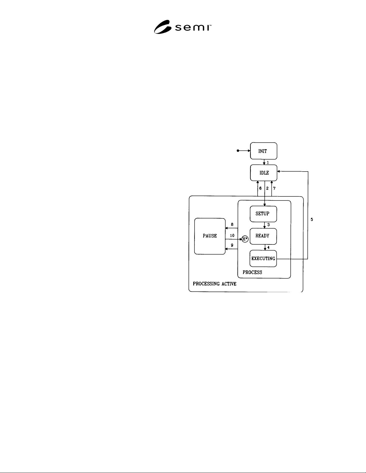
The Processing State Diagram, Figure 3.4, is provided
as an example of an implementation model. This model
demonstrates the expected nature of the processing state
model documentation. There is no requirement that
these specific states be implemented.
The equipment must generate collection events for each
processing state transition, as well as provide status
variables (ProcessState, PreviousProcessState) whose
values are the current processing state and the previous
processing state.
In referring to the Processing State Diagram, note that
the initialization state INIT is not an actual processing
state. It is shown here simply to indicate that the IDLE
processing state is entered upon completion of
equipment system initialization. On the following pages
detailed descriptions are provided for the equipment
processing states and state transitions (numbered) as
shown in the diagram.
3.4.1 Description of Equipment Processing States
IDLE
In this state the equipment is awaiting instructions.
PROCESSING ACTIVE
This state is the parent of all substates where the
context of process program execution exists.
PROCESS
This state is the parent of those substates that refer to
the active preparation and execution of a process
program.
SETUP
In this state all external conditions necessary for
process execution are satisfied, such as ensuring
material is present at the equipment, input/output ports
are in the proper state, parameters such as temperature
and pressure values are within limits, etc. If all setup
operations are already complete, then this becomes a
fall through state and a transition to the next state takes
place.
READY
In this state the equipment is ready for process
execution and is awaiting a START command from the
operator or the host.
EXECUTING
Executing is the state in which the equipment is
executing a process program automatically and can
continue to do so without external intervention.
PAUSE
In this state processing is suspended and the equipment
is awaiting a command.
Each state transition is defined in the following table.
Note that all transitions in this table should be
considered collection events.
Figure 3.4
Processing State Diagram